
SpinFire Web
Centro 7.5.0 and greater utilizes new technology to better serve and view SpinFire Web files. This will also allow Actify to build more functionality into SpinFire Web moving forward. This new SpinFire Web uses .scs files but can view the older .hwf format. Deployment scripts automatically update your previous pipelines using the CAD to SpinFire Web action to use the new .scs format.
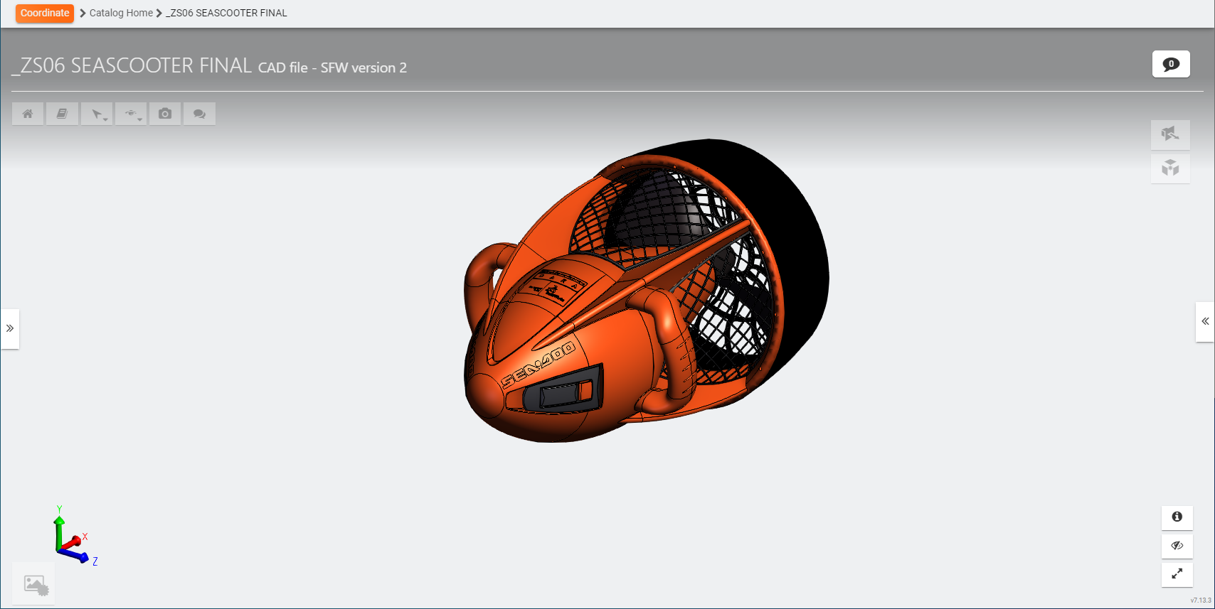
SpinFire Web allows you to view and comment on a 3D model. You can take a snapshot of the image at any time, save it to a file, and add it to the catalog.
Expand this tab by clicking on the orange tab 
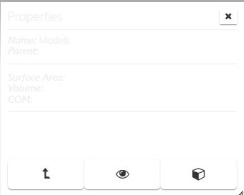
| Properties | Select a part to view the following:
|
| Select Parent | Click to move to the parent of the part. |
| Transparency | Turn a level of transparency on for the selected part. |
| Bounding Box | Select to show the axis-aligned bounding box. |
| Home | Click the Home button to reset the camera view back to the star. |
| PMI data | If the model contains PMI/GD&T data, toggle the information in the graphical view on and off. |


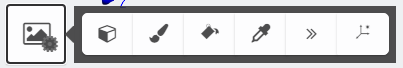
| Select Element Smart Edge Surface Angle Face Distance Point to Point Distance | Set to use the mouse to select parts of the model. Smart Edge Dimension Tool.
Surface Angle Dimension Tool.
Face Distance Dimension Tool.
Point to Point Distance Tool.
|
| Draw a Circle | Draw a circle to highlight a given area.
|
| Freehand Drawing | Use the Freehand Drawing tool to draw a line.
|
| Draw Rectangle | Draw a rectangle to highlight a given area.
|
| Draw Text | Place text anywhere in the model and create an associated User View.
|


| Orbit Part |
| Orbit Point |
| Turntable Camera |
| Walk |


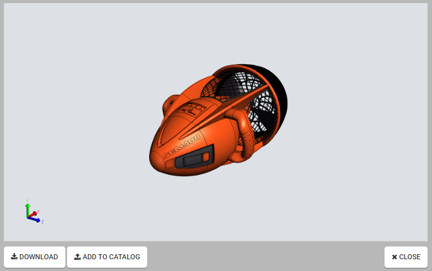
Take a snapshot image of how the model appears on screen.
Tip
Rotate, zoom, pan, change background color, and set your measurements and markups before taking your snapshot.
|
|

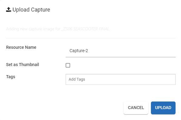
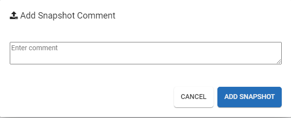
| Shared State Snapshot |
Take a snapshot image of the current state of the model in SpinFire Web, add it with a comment to the Comments section to collaborate with others in your organization. |

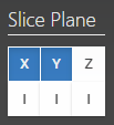
| Sectioning |
Select the X, Y, and/or Z axis to slice. One, two or all three planes can be used at once to section the model. Left-mouse-drag a section plane to move it across the model. Toggle the I button to flip the sectioning plane. |
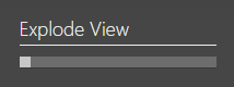
| Exploded Assembly |
Use the slider bar to increase the distance between parts and away from the center. |


| Perspective or orthographic projection | Click to toggle the project mode between perspective and orthographic. |
| Flat/Shaded (render mode) | Click to toggle the render mode between flat and shaded. |
| Change background color | Change the background color with a color selector. |
| Change Part Color | Click to select a color from the color picker to change the color of the selected part. |
| Momentum | Enable the momentum to auto-spin the model. Once enabled, hold the left mouse button down, move in a direction and release. The model will continue to spin. The model spins at a rate based on the speed the mouse was moving when the button was released. |
| Axis Triad | Toggles the axis triad off and on. |


| Properties Toggle - Hide/show the properties when clicking on a part. |
UI Toggle - Hide/show UI elements (browser, toolbars and tools) | |
| Fullscreen Toggle - Click to view the model in the browser's full screen mode. (In most browsers, This can also be achieved with the F11 key.) | |
- Use the breadcrumb path to navigate through pages you have visited.
- Click Part View to return to the part view.