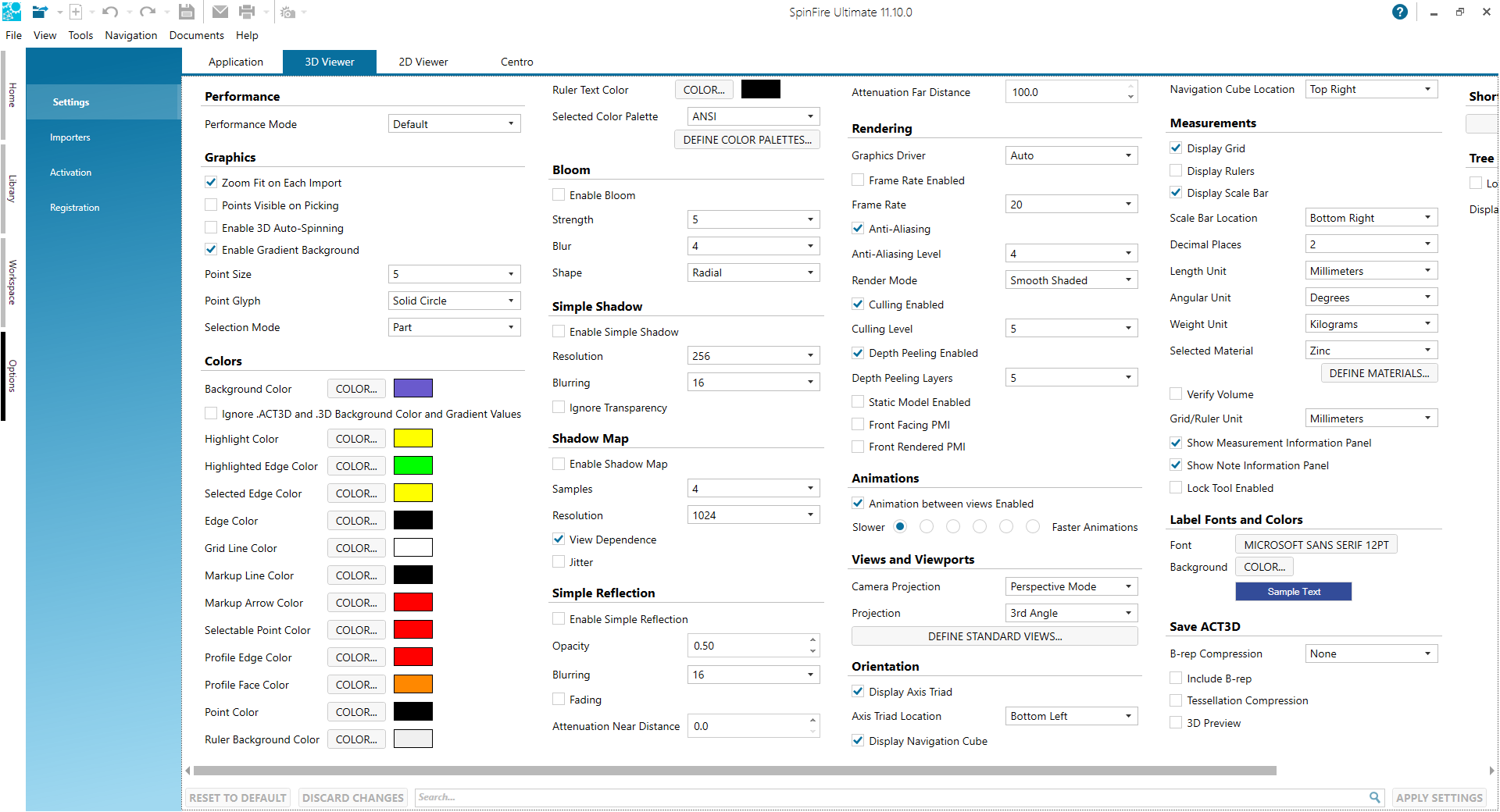
These settings affect the way SpinFire Ultimate displays your 3D images. You can specify how graphics behave, a color palette, special effects, how the model is rendered, animation speed, view and viewport features, measurement units and precision, and fonts and font colors. Simply select desired default 3D Viewer settings, then click the Apply Settings button. If you change your mind, click the Discard Changes or Reset to Default button.
Click on a link below to learn more about selecting 3D Viewer default settings:
Performance
Performance Mode - Select Default, Low, High, or create your own performance profile (Custom) to tune SpinFire Ultimate to your system's ability to render and load 3D files.
Zoom-fit on Each Import - When a file is opened, SpinFire Ultimate automatically pans and zooms to provide a close-up view of the document contents while still fitting the contents entirely within the Viewport. If the checkbox is cleared, the view will reflect the camera position of the original CAD file.
Points Visible on Picking - Makes vertex points visible as red dots during any command that requires a vertex to be selected.
Enable 3D Auto-Spinning - Causes a 3D model to spin continuously when rotated quickly.
Enable Gradient Background - The screen background is specified as a gradient.
Point Size - The size of a point in pixels.
Point Glyph - The shape of the point.
Values are Cross, Circle, Solid Circle, and Splat.
Selection Mode - The default object selection mode.
Values are Part and Surface.
SpinFire Ultimate .ACT3D files contain background information; default background settings do not apply to these files.
Colors
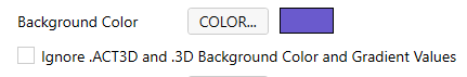
Background, Highlight, Highlighted Edge, Selected Edge, Edge, Grid Line, Markup Line, Markup Arrow, Selectable Point, Profile Edge, Profile Face, Point, Ruler Background, and Ruler Text Color colors - Click the respective Color... button to choose a default color for scene elements.
Selected Color Palette - From the drop-down menu, select a color palette for your scene. Also, you can create a new palette — or modify an existing one — by clicking the Define ColorPalettes... button.
Ignore .ACT3D and .3D Background Color and Gradient Values
Use this setting to ignore the background color saved in the .ACT3D or .3D file. It will use the Background Color set here in the 3D Viewer settings instead.
Bloom
Also know as glow or lightbloom. Bloom is used to reproduce the illusion of extremely bright light overwhelming the eye — the light in the bright background bleeds into the darker areas, such as a figure in a doorway.
Enable Bloom - The Bloom render effect is used as when loading a model.
Strength -The brightness of the bloom.
Values are 1 to 10.
Blur - The degree to which the bloom bleeds into darker areas (i.e., edges are softened).
Values are 1 to 8.
Shape - Specifies the shape of the bloom.
Values are Star or Radial.
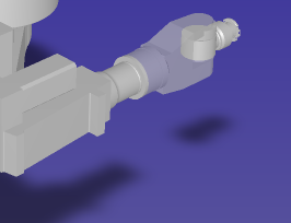
Simple Shadow
Creates a shadow cast by the model.
Enable Simple Shadow - The Simple Shadow render effect is used as when loading a model.
Resolution - Determines the sharpness and density of the shadow image.
Blurring - The degree to which the shadow edges are blurred.
Values are 2, 4, 8, 16, 32, 64, 128, 256.
Ignore Transparency - If selected, any transparent parts of the object will cast a shadow.
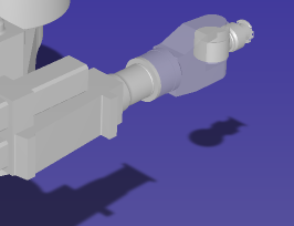
Shadow Map
Depending on the light source, SpinFire Ultimate will determine whether or not a pixel is in shadow and store this information as a numerical value in a shadowmap. The resulting shadows have jagged edges. In order to smooth the edges, random samples of values stored in the shadow map are averaged, which produces a shadow factor that can be used to smooth the border between light and shadow.
Enable Shadow Map - The Shadow Map render effect is used as when loading a model.
Samples - The greater the number of samples, the smoother the shadow edges, but the scene will take longer to render.
Values are 2, 4, 8, 16, 32, 64, 128, 256.
Resolution - The accuracy of the shadow map is limited by its resolution. Greater resolution uses more memory and can take longer to generate.
View Dependence - When enabled, the view is scaled and refreshed with the camera, ensuring consistent visuals in 3D View.
Jitter - When jitter is enabled, a randomizing function is applied to the process of determining where to take shadow map samples. Jitter may improve a scene visually by softening jagged shadow edges.
Simple Reflection
Creates a reflection of the model.
Enable Simple Reflection - The Simple Refliection render effect is used as when loading a model.
Opacity - The degree of non-transparency.
Blurring - The degree to which the reflection edges are blurred.
Fading - An gradient effect causing the reflection to appear as though it fades into the background.
Attenuation Near Distance - The distance between the light source and the model where the reflection begins to fade.
Attenuation Far Distance - The distance between light source and the model where the reflection is completely faded.
Rendering
Graphics Driver - Select a graphics driver from the drop-down list. SpinFire Ultimate supports OpenGL, OpenGL 2, OpenGL 2 Mesa, and DirectX 11.
Frame Rate Enabled - Use the Frame Rate field when checked.
Frame Rate - The number of frames of an animation displayed every second. The higher the frame rate, the smoother the animationwill appear, but processing power and system bandwidth requirements increase as well.
Values are 0 to 30.
Anti-Aliasing - By default, SpinFire Ultimate will smooth out any jagged diagonal or curved lines. Also known as dithering. Clear the checkbox to disable.
Anti-Aliasing Level - Set anti-aliasing to either 2, 4, or 8. The default is 4.
Culling Enabled - Enables culling when set. Used with the Culling Level setting.
Culling Level - This is the size in pixels which objects are drawn. Smaller the objects drawn with larger the culling levels may be reduced to not appearing on screen. Larger culling levels may improve drawing performance.
Default value: 20.
Depth Peeling Enabled - Enables depth peeling when set. Used with the Depth Peeling Layers setting.
Depth Peeling Layers - Indicates the number of layers of overlapping transparency used when drawing objects. The smaller the value, the better the performance.
Default value: 5.
Static Model Enabled - Enable to boost performance with pan/zoom/rotate. Usage may negatively effect other functionality.
Front Facing PMI - Enable to have PMI text always front facing despite flipping and rotating of the model.
Front Rendered PMI - Enable for PMI to always be in front.
Animations
Animated between views Enabled - When enabled, transitioning to a User view is smoothly animated.
Animation Speed - Select 1 of 6 different speeds to animated User view transitions.
Views and Viewports
Display Grid - When enabled, Front, Back, Top, Bottom, Right, or Left standard views include a background grid.
Camera Projection - Determines how objects are viewed. In perspectivemode, grid lines converge to a vanishing point. This provides the illusion of depth in the viewport; objects farther away look smaller. In parallelmode, all the grid lines are parallel to each other, and identical objects look the same size, regardless of where they are in the view.
Values are Perspective Mode, Parallel Mode.
Projection - Determines the orthogonal projection method used when the model is displayed in 4 Viewport and 3+1 viewport modes.
Values are 1st Angle (4 Viewport: Left , Top, front, isometric; 3+1 Viewport: Bottom, Front, Top, lg isometric) 3rd Angle (4 Viewport: Right, Bottom, Front, isometric; 3+1 Viewport: Top, Front, Bottom, lg isometric).
Orientation
Axis Triad Enabled - Specifies whether or not the coordinate system triad (frame) is displayed in the scene.
Axis Triad Location - Specifies where in the scene the coordinated system triad is located.
Values are Top Right, Top Left, Bottom Right, Bottom Left.
Navigation Cube Enabled - Specifies whether or not the navigation cube (point-of-view quick reference) is displayed in the scene.
Navigation Cube Location - Specifies where in the scene the navigation cube is located.
Values are Top Right, Top Left, Bottom Right, Bottom Left.
Measurements
Decimal Places - Determines the default number of decimal places that are displayed in measurement labels.
Angular Unit - Specifies the default unit of measurement for angles.
Values are Deg-Min-Sec, Radians, Degrees, Grads.
Weight Unit - Specifies the default unit of measurement for weight.
Values are Ounces, Megatonnes, Kilotonnes, Tonnes, Kilograms, Hectograms, Decagrams, Grams, Decigrams, Centigrams, Milligrams, Nanograms, Short Tons, Pounds, Long Tons.
Selected Material - Click to choose a construction material from the drop-down list. If you add a material to the materials list (see Define Materials...), it will also appear on the list.
Define Materials... - Click to add a definition to the materials list.
Verify Volume - When enabled, the model is verified to be a closed solid when its volume is calculated.
Ruler Enabled - When enabled, the ruler appears in orthographic views.
Scale Bar Enabled - When enabled, the scale bar appears in 3D documents.
Scale Bar Location - Specifies where in the scene the scale bar is located.
Grid/Ruler Unit - The default unit for 3D grids/rulers.
Show Measurement Information Panel - When enabled, the instructional dialog window(s) and the final dialgo window for measurements appears.
Show Note Information Panel - When enabled, the instructional dialog window(s) and the final dialgo window for notes appears.
Lock Tool Enabled - When enabled, the "Lock tool" checkbox is checked for measurements and notes. A locking tools allows use of the measurement or note feature repeatedly without re-initializing it.
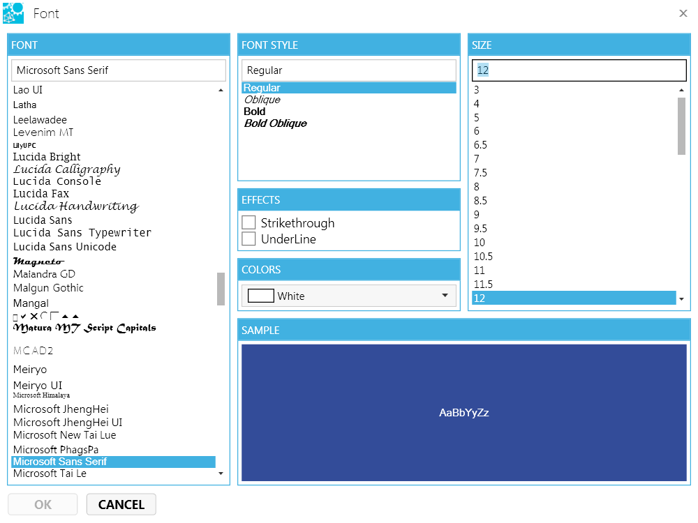
Label Fonts and Colors
Font - Click the Font name (default is Microsoft Sans Serif 12 pt) to select font, font style, size, effects, and color for markup and measurement labels.
Background - Click the Color... button to select the background color for markup and measurement labels.
Fonts and and background color for individual markups and measurements can be changed from the toolbar.
B-Rep Compression - Set the level of boundary representation (B-Rep) data compression.
Values are: None, Low, Medium, High.
Include B-Rep - When enabled, B-Rep information is preserved when file is saved. The B-Rep provides greater accuracy when measuring volumes and curved surfaces, but increases file size.
Tessellation Compression - When enabled, tessellation is compressed when the file is saved, which results in a smaller file size (but accuracy is diminished).
3D Preview - When enabled, 3D preview data is included when the file is saved.
Shortcut Toolbar
Define Shortcut Toolbar - Add, edit, delete to the shortcut toolbar to increase personal productivity. Export and export features are available to share a shortcut toolbar configuration with colleagues or to yourself on a different system(s).
Tree Management
Load Surfaces on Demand - When enabled, surfaces on not loaded during the opening of a 3D model file. Surfaces are brought in on demand (i.e - the assembly tree is expanded to those areas). This is disabled by default.
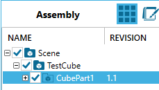
Display Tree Attribute Name - Fill this field with an atribute found in the CAD file. The attribute appears as a new column in the assembly tree of SpinFire Ultimate.
The same information is seen in the Properties of a part but having the value appear in the assembly tree is far more convenient.
Consider using this setting with the Attributes importer option.
For example, an organization may work with CAD files where an attribute, "Revision", is required. Entering "Revision" in the Display Tree Attribute Name field cause the value(s) of the Material attribute from the CAD file to be displayed in the SpinFire Ultimate assembly tree as a column.
Import, export, and reset SpinFire Ultimate settings
You can save your current Application, 3D Viewer, and 2D Viewer settings to an XML file. Another user can then load this XML file to use the same Application, 2D, and 3D Viewer settings in his/her SpinFire Ultimate environment. This can be useful if a file requires specific settings in order to be viewed properly or if an organization needs to ensure that all users are using the same settings.
Save a viewers settings file
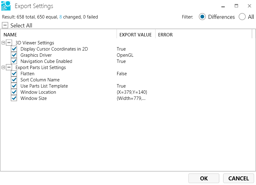
From the menu bar, select Tools > Export Settings...
On the Export Settings dialog box, select/clear checkboxes corresponding to the settings you would like to save.
Click OK toopen the Windows Save As dialog box. The settings file name extension is .config.
Open a viewers settings file
From the menu bar, select Tools > Import Settings....
Navigate to and select the file, then click the Open button (or simply double-click the file name). The settings file name extension is .config.
The Import Settings dialog box appears, which lists existing and new setting values side by side. If the new settings are acceptable, click the OK button. (Note the Filter radio buttons: You can choose to view only the differences between the existing and new settings to more easily compare the values.)
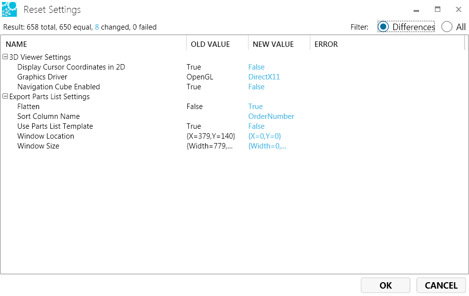
Restore settings to original defaults
From the Menu toolbar, select Tools > Reset Settings....
The Reset Settings dialog box appears, which lists existing and original default setting values side by side. Click the OK button to restore the original defaults. (Note the Filter radio buttons: You can choose to view only the differences between the existing and new settings to more easily compare values.