Draft Angle Analysis
Overview
The Draft Angle Analysis allows the user to easily analyze a part for proper draft angle.
A Draft Angle describes the amount of taper for molded or cast parts perpendicular to the parting line.
To access the Draft Angle Analysis (DAA) feature, select Draft Angle Analysis from the 3D menu.
Note
Draft Angle Analysis is applicable only for 3D documents. An active 3D workspace is required to initiate the Draft Angle Analysis feature.
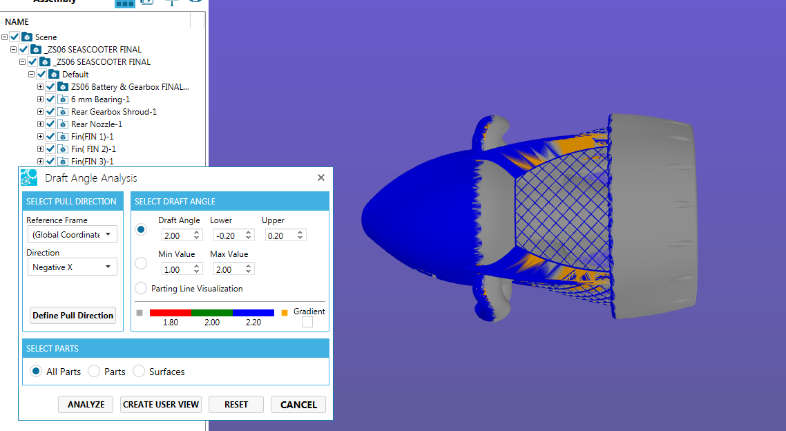
Draft Angle Analysis panel opens.
To create a Draft Angle Analysis for any 3D file, the user needs to:
- Select Pull Direction
- Select the Draft Angle
- Select Parts/ Surfaces
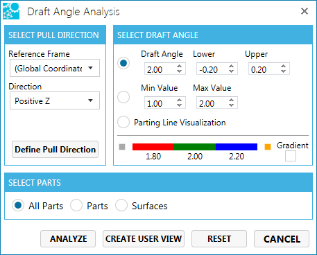
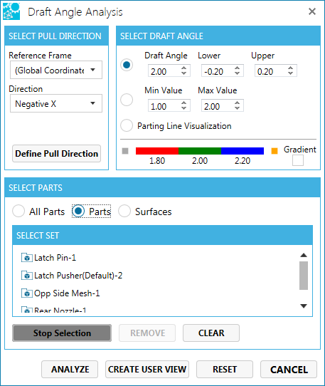
Select Pull Direction
The Pull Direction is defined as the axis against which the angular values specified in the dialog box will be evaluated. By default the Reference Frame selects the World Reference Frame and positive Z direction as the default.
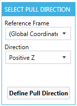
- The user can also select the different direction on the world reference frame by simply using the Direction drop-down and choosing the desired direction.
- If another reference frame has been created, the user can also select any direction against that reference frame by using the Reference Frame Pull drop-down and then making the appropriate Direction selection, if required.
- If an appropriate coordinate system does not exist, the user can click Define Pull Direction button, select a surface and a new coordinate system is created.Note: When the user clicks Define Pull Direction button, the dialog box changes to ‘Pick on a Surface’.
Select Draft Angle
The three options are as follows.

Delta:The user can select the Draft Angle, Upper and Lower limits of tolerances.The user can select the desired draft angle to be used for analysis. The default Draft Angle is 2.00 degrees. The draft angle can be changed (increased/ decreased) in increments of tenths of a degree with the help of buttons, or by typing a value inside the text box.
Note
If a new value is selected for the Draft Angle, the scale below the parameter settings changes accordingly.
- Limit: Defines the Minimum Value and Maximum Value of draft angle extremes.Min value: This is the lower boundary of the analysis, expressed in degrees of variation from the pull direction, and can be a positive number, negative number, or zero.
Max value: This is the upper boundary of the analysis, expressed in degrees of variation from the pull direction, and can be a positive number, negative number, or zero.
Note: There is no “tolerance” in this specification as there is in the basic mode.
Gradient: Selection of Gradient specifies a range of deviation from the pull direction, and have the analysis report the results. This option is useful where the effects of a compound surface or a set of surface transitions (such as seen in the blends of a boss with a side wall and a floor of a pocket) need to be analyzed. - Parting Line Visualization: Sets the analysis tolerance to zero. Any surface with non negative (zero or greater) draft will be green while surfaces with negative draft will be red. The partying line is represented by the transition between red and green. Also if there is any red surrounded by green, then there must be some tooling allowance made to accommodate it through the use of slides, lifters or core pins. No geometry is created representing the parting line.Note: When Parting Line Visualization is selected, Gradient option will be grayed out.
Preview Bar:
Preview Bar displays the colors depending upon the value selected in the draft angle, min value and the max value.
Note
To change the color scale double-click on the color component (for Delta and Limit settings, there are three color regions and for Parting Line Visualization, there are two), this displays the dialog box. Choose the desired color and the scale will change accordingly.
Select Part
This option allows the user to select Parts or Surfaces.
Select Part supports three options:
- All Parts: All parts visible in the scene will be analyzed. The default is All Parts.
- Select Parts: The user can select a part or a set of parts for any single analysis. When this option is selected, the assembly tree is displayed.
** Pick a vertex point on the part in the active workspace.- Pick the part by selecting on the appropriate node in the assembly tree.
- Select Surfaces: The user can select a surface or a set of surfaces for any single analysis.
Entity Count: The test box displays the total number of entities selected (parts/ surfaces).
Views
- Click Create User View to save the view for further reference.This displays a pop-up.
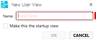
- Enter the View Name.
- Click OK to save the view name.
- Click Restore View to restore the view without saving the result.
- Analyze/ Apply : This button will kick start the analysis based on the user selected “Draft Angle”, “Select Part” options on the selected individual Part(s) or Surface(s). Apply button would initiate the analysis which will change surface colors of the selected parts or surfaces to communicate the Draft Angle Analysis results.
- Reset: It would clear any surface or part selections made by the user and would reset the “Entity Count” to zero. The surface analysis colors are reset.
- Cancel: It will close the DAA interface and bring the focus back to SpinFire window. The current view orientation will not change. The colors will be reset, unless the user had saved the view.