
Coordinate Systems in a 3D Scene
Users can define their own coordinate systems and include multiple coordinate systems in a 3D scene.
Every scene viewed in SpinFire Ultimate contains the Global Coordinate System, which defines the (0,0,0) point and the direction of the x-, y-, and z-axes. You can also include additional coordinate systems with your own positions and orientations. The Markups pane lists all the coordinate systems in a scene.
Like markups and views, coordinate systems are included when you save a model in Actify's .3D file format.
Creating and Editing a Coordinate System
To create or edit a coordinate system, you will use the Coordinate System dialog box. (See Working with Coordinate Systems for step-by-step instructions.)
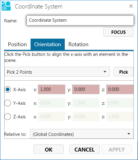
The Coordinate System dialog box contains the Position, Orientation, and Rotation tabs, which set the location and direction of the coordinate system. Both the Position and Orientation tabs offer two methods for defining position and orientation: either pick an element in the scene or enter precise figures into the dialog box.
Set the origin point of the coordinate system, either by selecting a point or circle on the model or by entering the distance the origin point will be offset with respect to the origin point of another coordinate system. (See Working with Coordinate Systems for details.)

Set the x-, y-, or z-axis by clicking two points on the model or an axis of another coordinate system. Or, you can set the axis by entering the values of a vector relative to another coordinate system. (See Working with Coordinate Systems for details.)
Set rotation axis and angle. (See Working with Coordinate Systems for details.)

Note
The Global Coordinate System cannot be edited or deleted.Quick Links
The Active Coordinate System
At all times, one of the available coordinate systems is designated as the active coordinate system. The triad for the active coordinate system appears larger in the 3D scene and its name is in bold text on the Markups pane. You can designate any coordinate system as the active coordinate system by right-clicking it and selecting Active Coordinate System. (See Working with Coordinate Systems for details.)
The active coordinate system affects part rotations, part translations, and certain dimension measurements. By default, these commands are performed with respect to the active coordinate system.
Certain dimension markups take their measurements with respect to the coordinate system that is active at the time the markup is created. When the active coordinate system changes, the dimension label will not change—it will still display the measurement with respect to the coordinate system that was active when the dimension was created. However, you can change the coordinate system by which a dimension markup is measured by using the markup Properties dialog box. (See Working with Coordinate Systems for details.)
When using the Rotate or Translate command to position a part, you may select a coordinate system other than the active coordinate system from the "Relative To:" drop-down menu. (See Assemblies and Parts in a 3D Scene for details.)