Assembly Context Menu
Commands for working with an object assembly, subassemblies, parts, and surfaces are available from the assembly object context menu. Right-click an object in the Assembly browser or the viewport to access the menu.
To select multiple objects:
- Assembly Tree (see Browsers) - SHIFT+click objects, then right-click.
- Model - CTRL+right-click (pick parts one at a time) or SHIFT+right-click+DRAG (multiple part selection).
Note
The Rename and Properties functions are not available when selecting multiple parts.
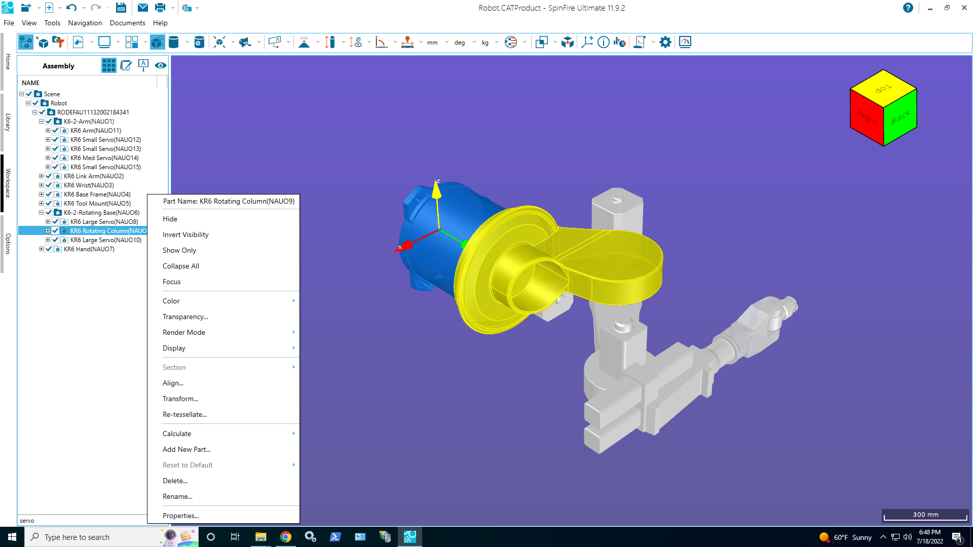
The following commands are available from the assembly object context menu:
Choose whether you want a new color applied to the front (exterior) of the object, the back (interior), or both.

Set the transparency value of the object.
![]()
Specify how the object is drawn.
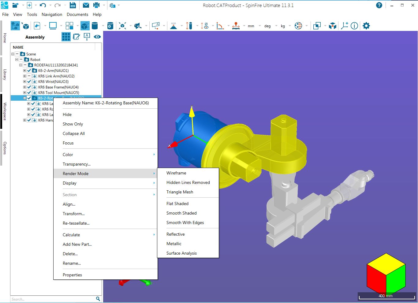
Hidden Lines - Similar to wire frame but the segments are not transparent.
Triangle Mesh - Outline of the triangles used to establish the shading.
Flat Shaded - Triangles are colored but the edges of the triangles are visible.
Smooth Shaded - The edges of the triangles are smooth. This is the default render mode.
Smooth with Edges - Smooth shading with highlighted edges.
Reflective - Shiny metallic rendering.
Metallic - Dull metallic rendering.
Surface Analysis - Reflective rendering for analyzing surface irregularities.
Show/hide points on the part, wireframe, and all surfaces and solids.

Show/hide cut material or change the profile color.

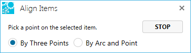
Enables you to directly align two parts to the same location. Align by three points or by an arc and a point. See Align Models.
Enables you to reposition the model or part(s) in the scene. Move, Rotate, From/To, and Mirror give you precise control. Handles allows you to manually reposition the part.
![]()
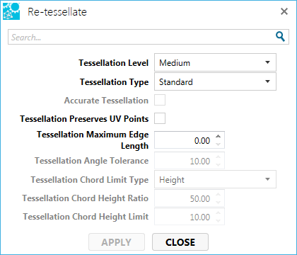
Enables you to change the tessellation quality on a part withing the work space. See Re-Tessellate.

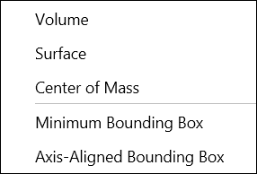
The Minimum Bounding Box calculation finds the dimensions of the smallest box that could surround an object (irrespective of axes alignment). In the example below, the Reducer sample model has been transformed 45 degrees on the X, Y, and Z axes so it is no longer axis aligned. Notice how the Axis-Aligned Bounding Box is calculated.

Note
The calculated volume is more accurate than multiplying DX x DY x DZ due to precision of the volume calculation compared to rounding discrepancies using DX, DY, and DZ values.
The Axis-Aligned Bounding Box calculation finds the dimensions of the smallest box that could surround an object where the bounding box is aligned with the X, Y, and Z axes.

Note
The calculated volume is more accurate than multiplying DX x DY x DZ due to precision of the volume calculation compared to rounding discrepancies using DX, DY, and DZ values.
Enables you to remove an assembly tree item. This can be an assembly, sub assembly, part, solid, or set.
When deleting a part, one will always be given a confirmation message before actual deletion occurs.

Rename the object. When selected, the object name becomes editable. Type the new name and press Enter.

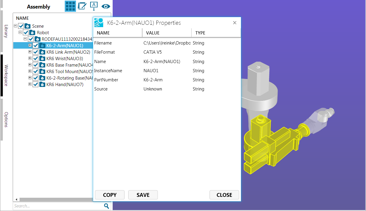
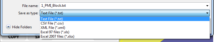
Display object properties (metadata). You can Copy the metadata to the Windows clipboard for use in other applications or Save it as a .txt, .csv, .xml, .xls (Excel 97), or .xlsx (Excel 2007) file.
Switch to another part with the dialog remaining open by simply selecting another part.