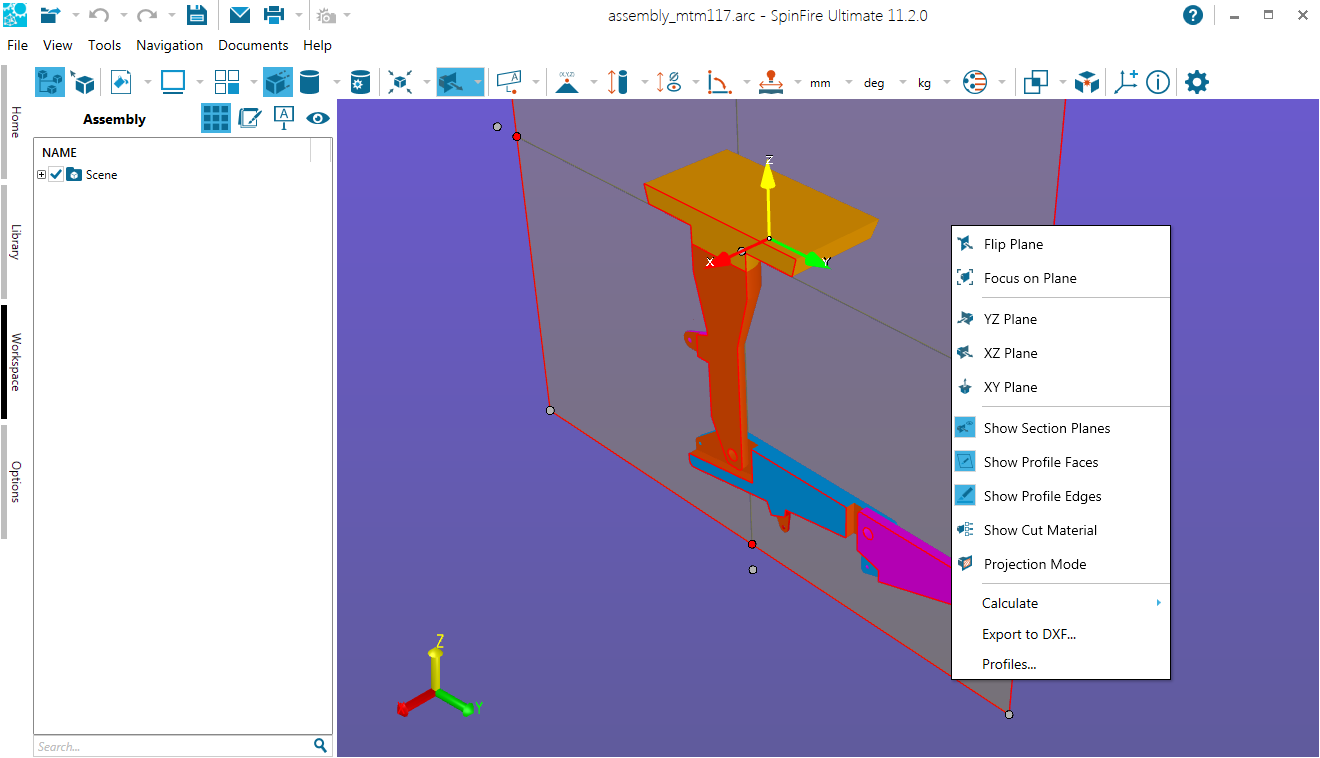
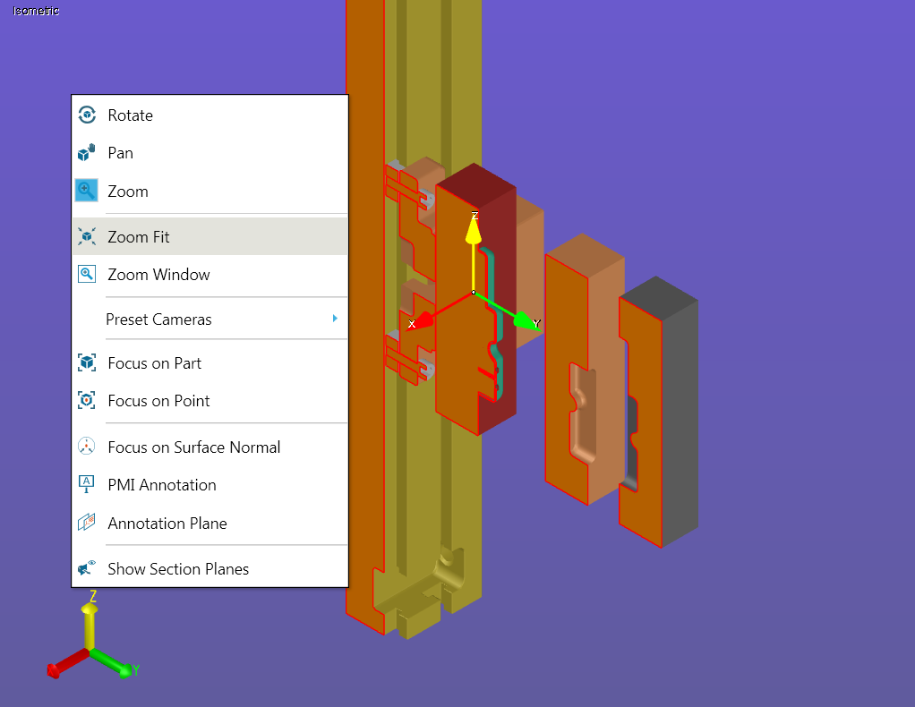
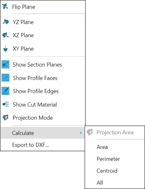
The Cross Sectioning Context Menu
The cross section context menu enables you to manipulate the selected plane; for example, you can flip the view or change the plane axis. It also provides another means to access the Define Section dialog box and the Projection Area Measurement function (described in Cross-Sectioning a 3D Model).
The context menu can be accessed by right-clicking the plane itself.
The Flip Plane function changes the cut from one side of the selected plane to the other.
Sets focus to the section plane.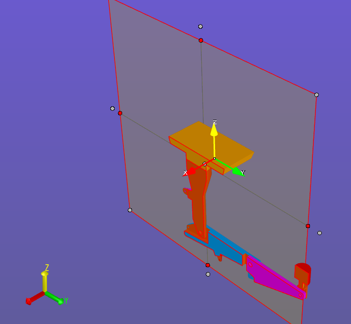
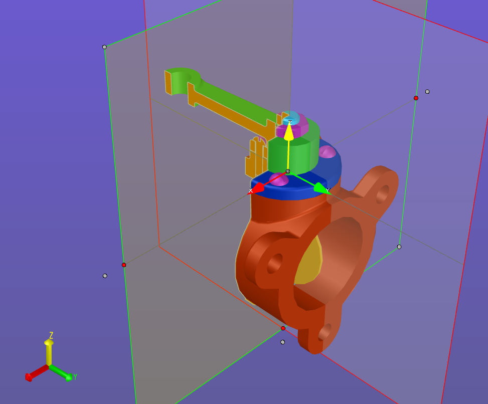
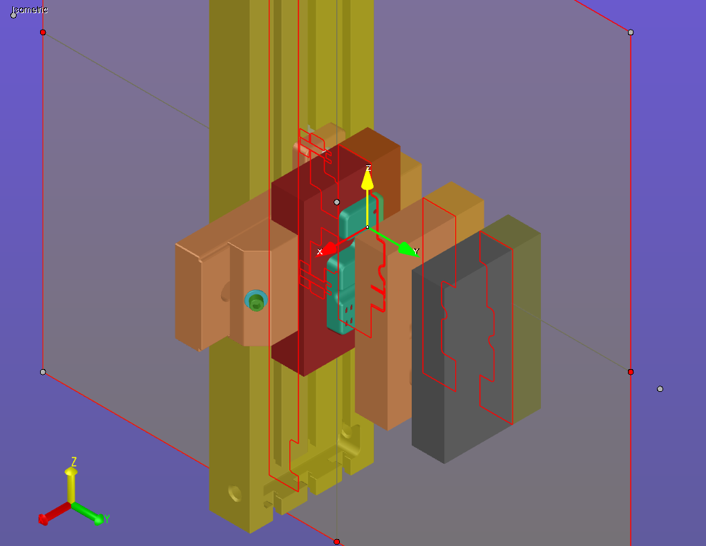
Show Section Planes - Show/hide the cross-section plane(s). The cross-section plane normally appears as a transparent gray rectangle.
See Cross-Sectioning a 3D Model Define... to learn about changing default settings.
To restore a hidden section plane, right-click anywhere in the background to view the scene context menu. Note that the option to show/hide section planes has been added to the menu. This selection is available only when sectioning is enabled.
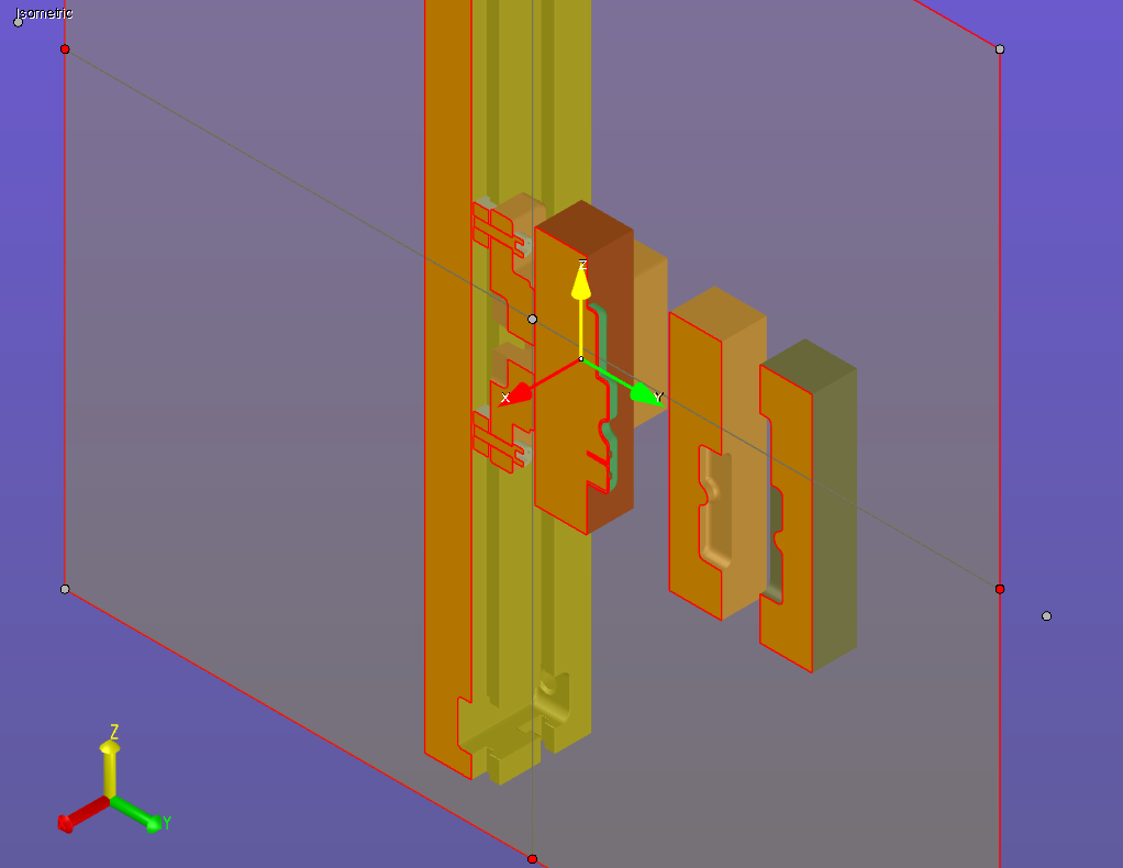
Show Profile Faces - Show/hide profile faces for the entire scene; by default, Show Profile Faces is enabled.
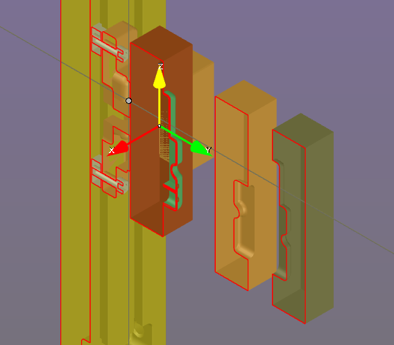
See Cross-Sectioning a 3D Model Define... to learn about changing default settings.
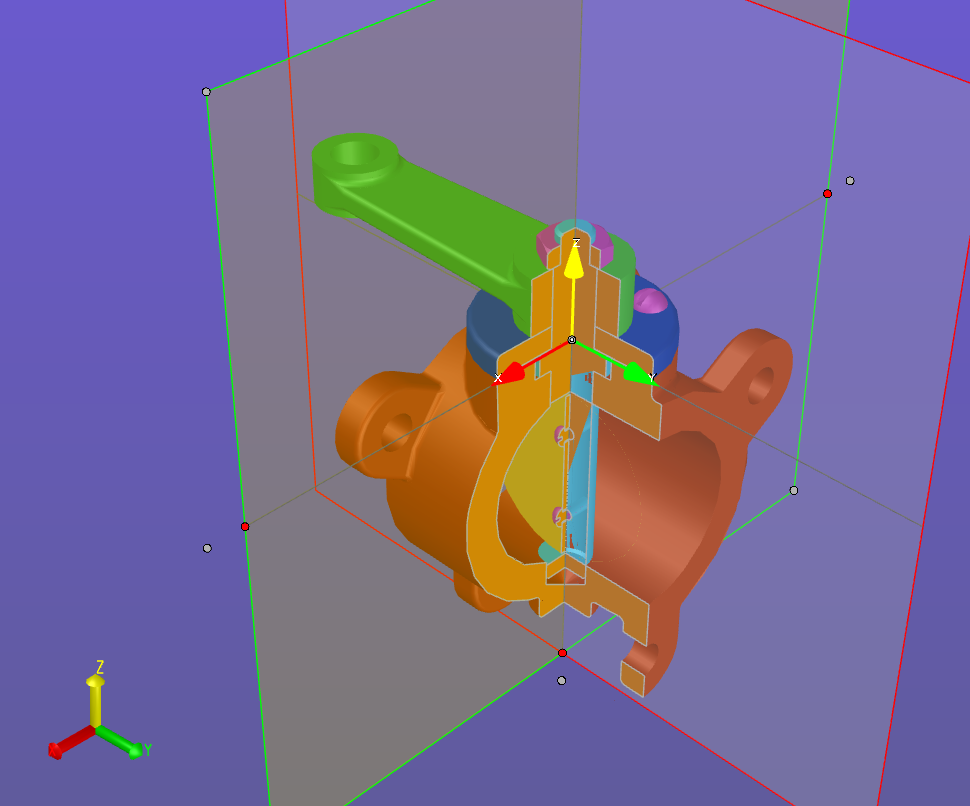
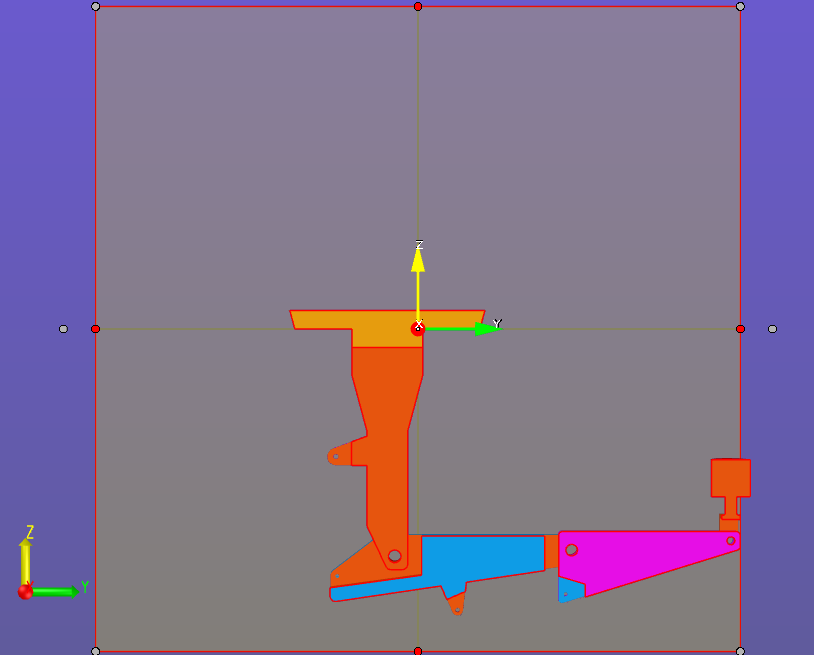
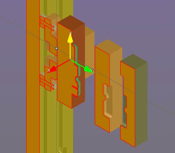
Show Profile Edges - Show/hide profile edges. The section profile is an outline of all the points on the model that intersect with the section plane—by default, it is outlined in red.
See Cross-Sectioning a 3D Model Define... to learn about changing default settings.
Note
If you wish to see just the profile outline, without any of the related geometry, select Cross-Section from the Standard Views options in the Views browser (see Controlling the View).
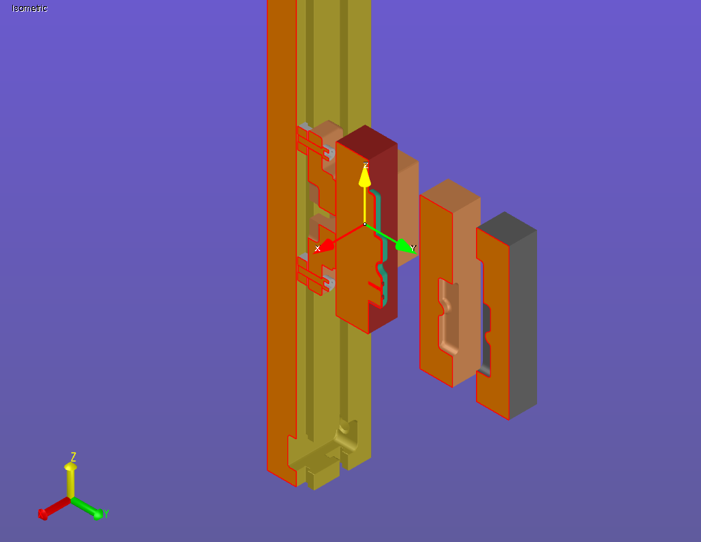
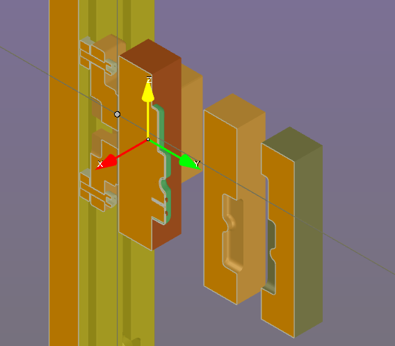
Cut Material - Show/hide model on one side of the section cut. By default, the Cut Material is hidden, which means that the cross-sectioned model will be visible on one side of the plane and not visible on the other.
Also, you can turn on/off Cut Material for just selected parts or subassemblies (see Assembly Object Context Menu).
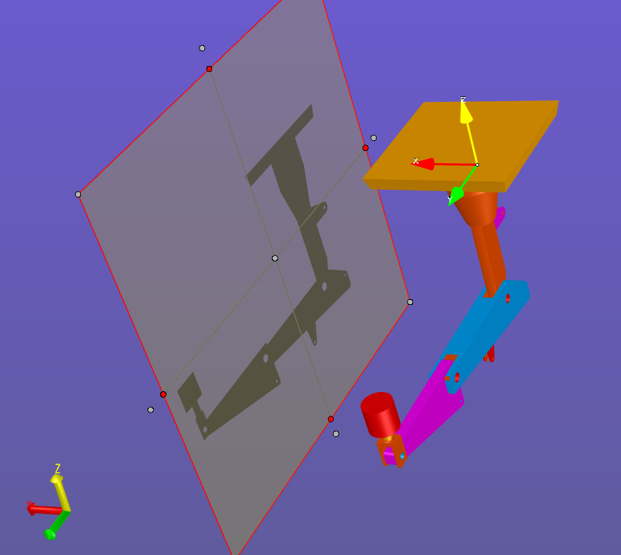
This selection enables users to easily view and then calculate the area of a model's projection on a plane. The projected surface area is very useful in sheet metal–forming applications to calculate the necessary press tonnage.
Control of the projection plane is the same as that of the cross-section plane.
Warning
When the projected area is calculated, only the portion included on the plane will be used to calculate the surface area. So if the projection falls off of the plane, be sure to move the plane such that the entire part appears on the projection plane.
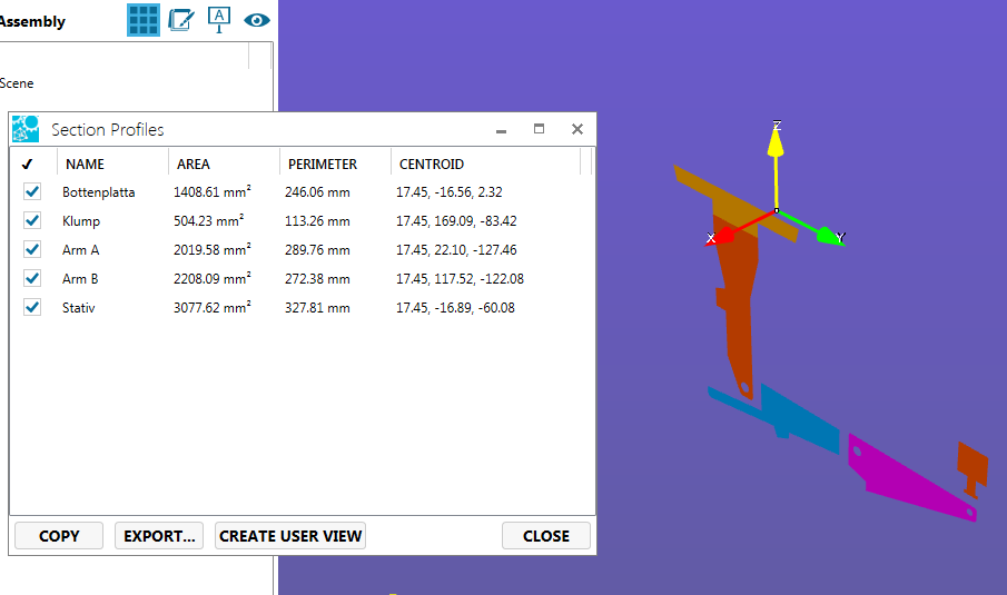
Select Calculate to measure the cut area, perimeter length, and center point. If Projection Mode is enabled, you can also determine the area of the projection.
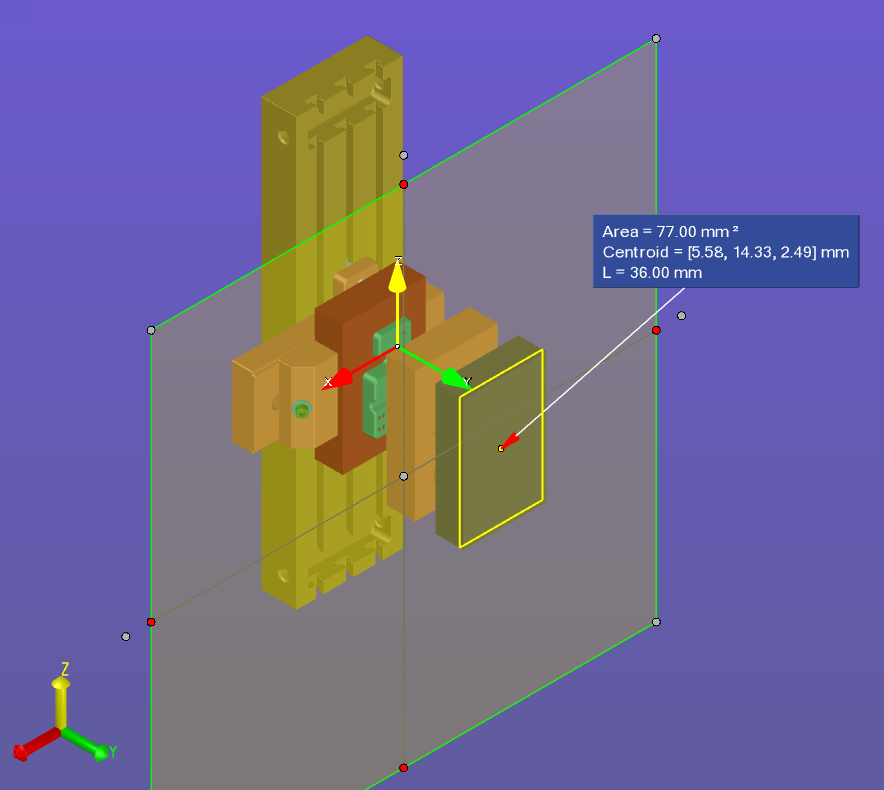
Calculate the area, perimeter, centroid for any of the section profiles singularly or in combination.