
Cross-Sectioning a 3D Model
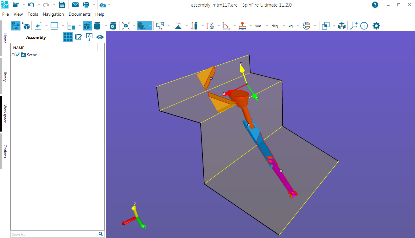
The capability to display a cross section of a part or assembly is one of the most important and useful features of SpinFire Ultimate. Mechanical designers look at cross sections in order to better understand the structure of a part and hidden components in an assembly.
The Section menu on the 3D Document Toolbar lists the commands available for cross-sectioning planes.
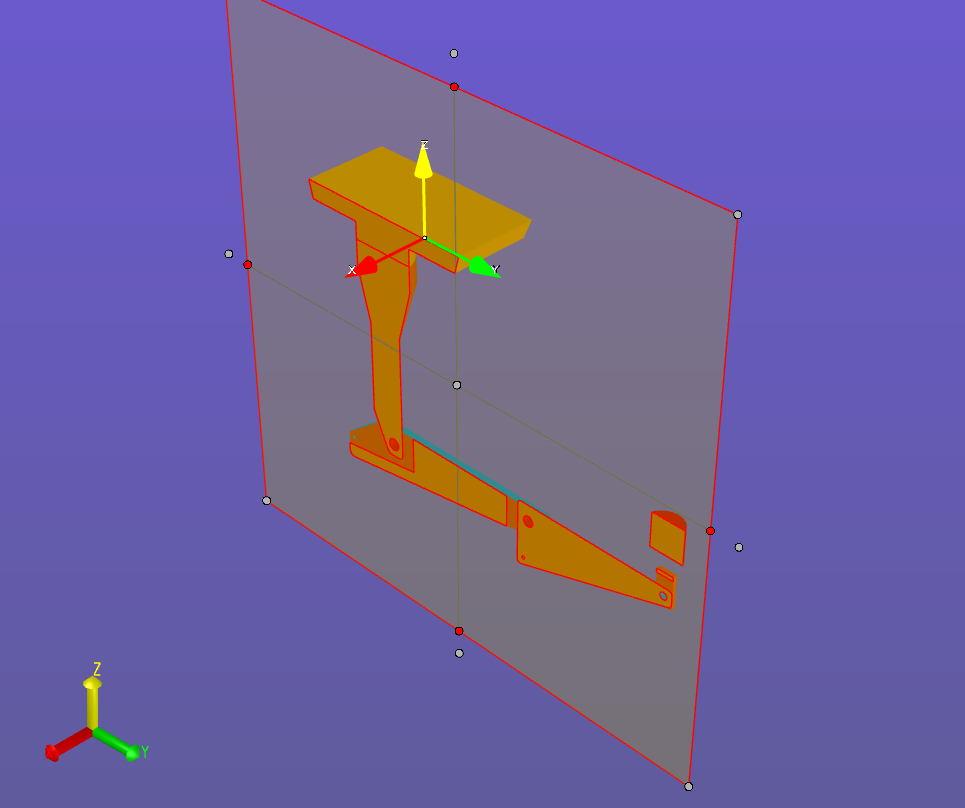
Enable/Disable Section turns cross sectioning on/off. A cross-section plane shows the model as if it has been cut straight through.
By default, the Enable Section command will show a single plane; the section is transparent and you can see into the model. (See also Working with Cross Sections.)

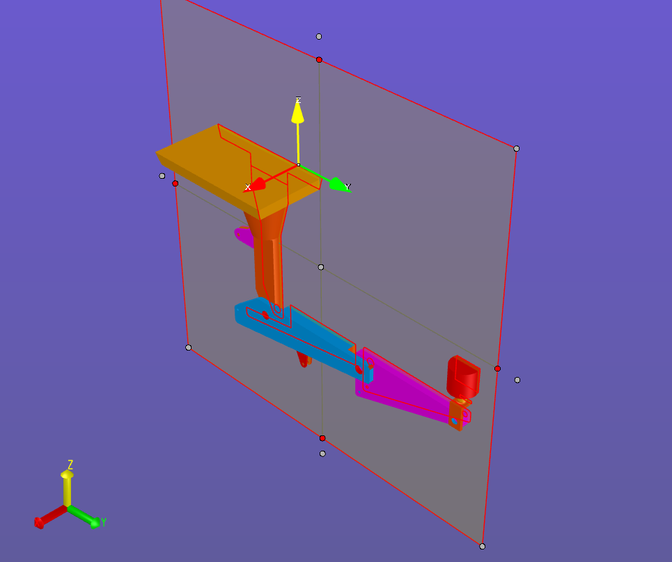
By default, a cross-sectioned model will be visible on one side of the plane and invisible on the other (see also Cut Material). The Flip Section command enables you to switch between these two views.
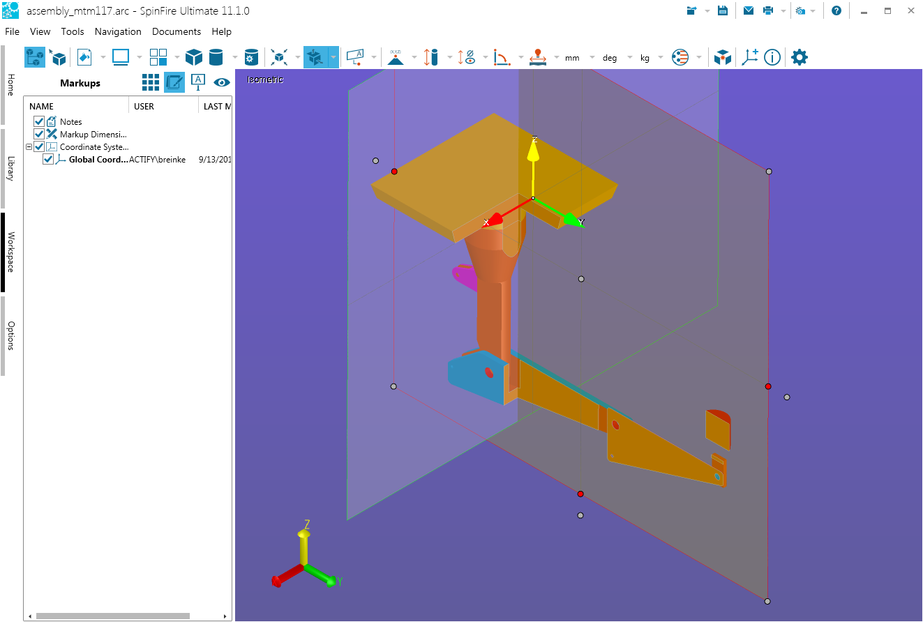
By default, the Enable Section command will show a single plane (shown below). Use the Two Plane and Three Plane commands for more cross-section options. The most recently selected command is displayed on the 3D Document Toolbar. (See also Working with Cross Sections.)
By default, the Enable Section command will show a single plane. Use the Two Plane (shown below) and Three Plane commands for more cross-section options. The most recently selected command is displayed on the 3D Document Toolbar. (See also Working with Cross Sections.)
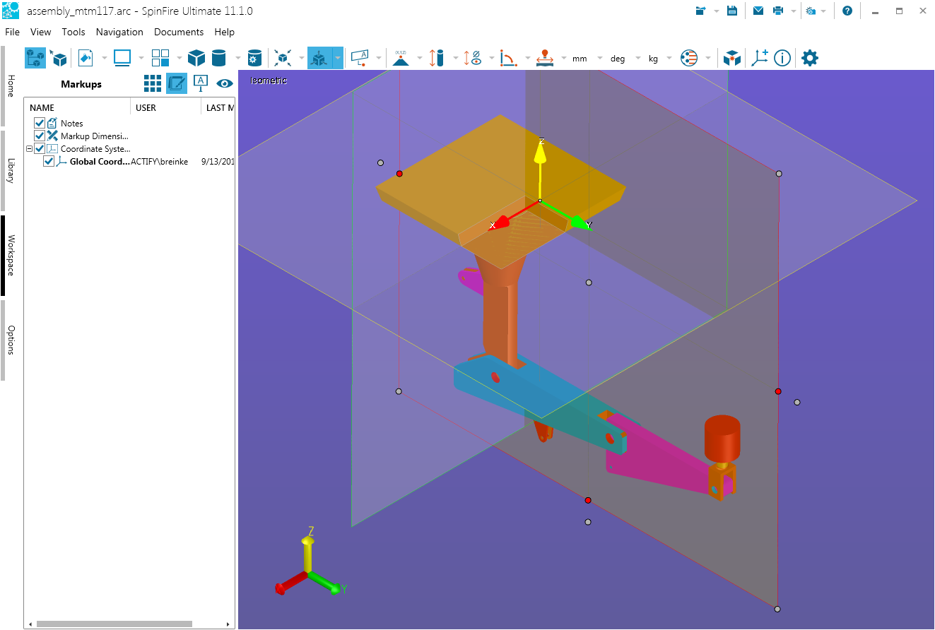
By default, the Enable Section command will show a single plane. Use the Two Plane and Three Plane (shown below) commands for more cross-section options. The most recently selected command is displayed on the 3D Document Toolbar. (See also Working with Cross Sections.)
By default, the Enable Section command will show a single plane. Use the Offset Section (shown below) command for a stepped section. The most recently selected command is displayed on the 3D Document Toolbar. (See also Offset Sectioning.)
By default, the cross-section plane will be bounded by the YZ axis that passes through the (0,0,0) point of the global coordinate system. Use the Settings, Movement, Position, and Orientation, and options (tabs on the Define Section dialog box) to precisely define other viewpoints and settings. (See also Working with Cross Sections.)
Use these options to change default color settings, show/hide section planes, and "cycle" through 1-, 2-, and 3-plane sections and viewpoints.

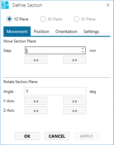
Move or rotate an enabled plane a certain number of units along its axis.
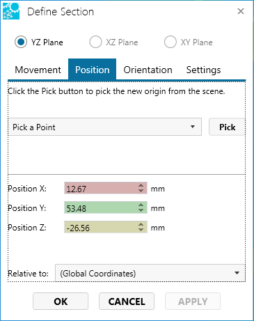
Choose a point the plane will intersect. Specify a point by entering its coordinates in the X, Y, and Z fields, or click the Pick button to specify the point in the scene directly.
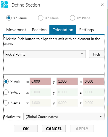
Orient the plane with respect to a specified element. Alignment may be specified by entering vector values in the X, Y, and Z fields, or by choosing an option from the drop-down menu.
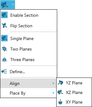
The Align flyout menu lets you choose the plane to intersect a selected point on the model.
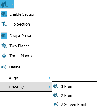
The Place By flyout menu offers the following commands for defining a plane:
- 3 Points - A plane defined by three points that you select on the model.
- 2 Points - A plane that is perpendicular to a line defined by two vertices that you select on the model. The initial plane will pass through the first vertex you select.
- 2 Screen Points - A plane that is parallel to the line defined by any two points that you select in the viewport. The two points do not have to be vertex points and do not have to be on the model. The initial plane will pass through the two points you select.
Related Topics
The Cross Sectioning Context Menu
