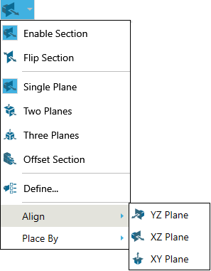
Click the Enable Section icon on the 3D Document Toolbar to display the cross section(s). Click it again to hide the cross section(s).
The default setting is Single Plane ( ). SpinFire will "remember" the most recently used setting.
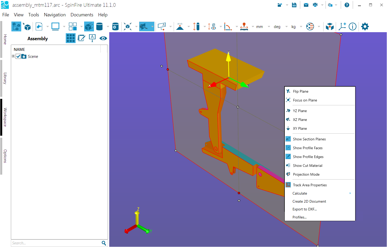
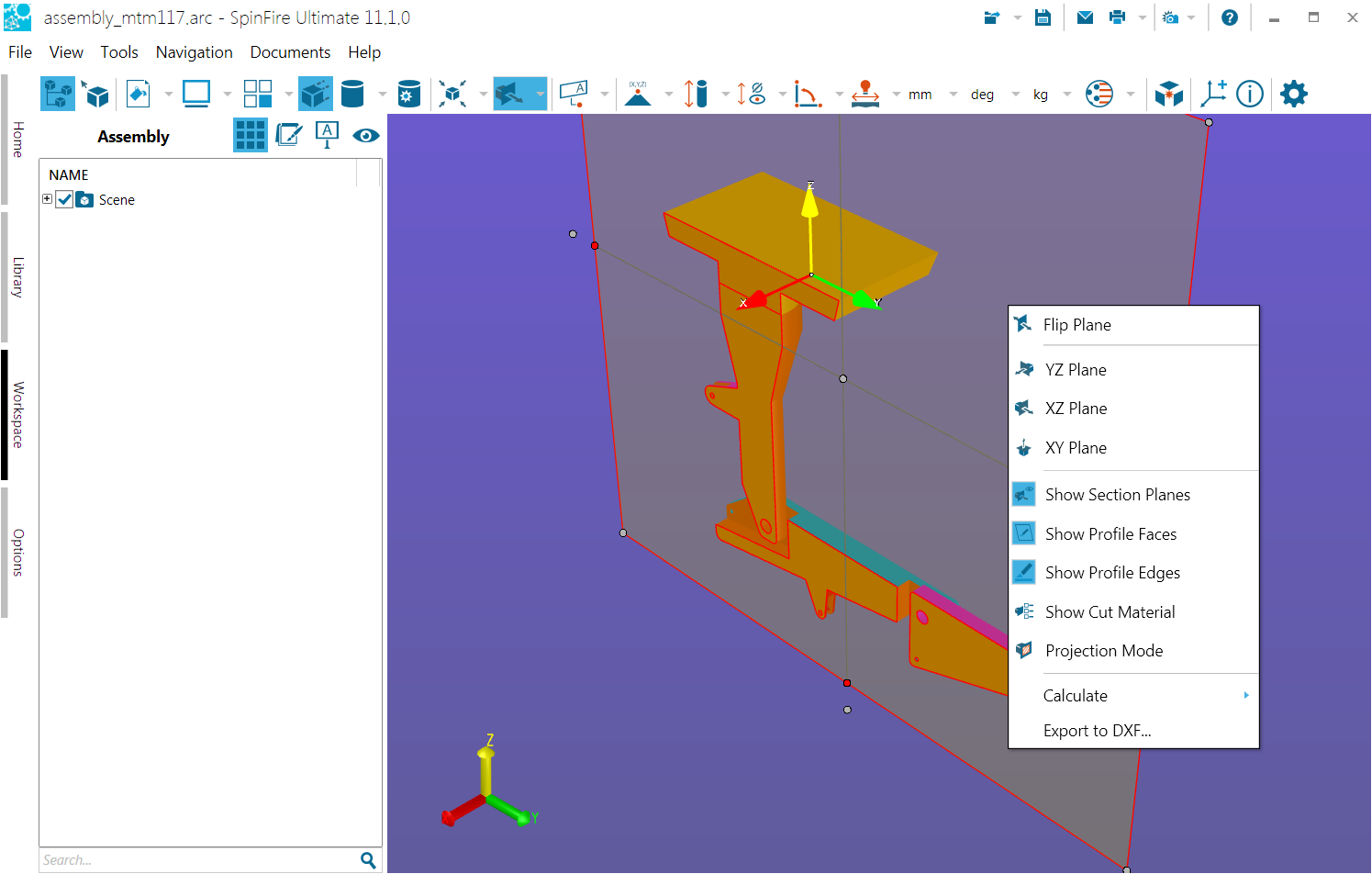
Show or hide section planes
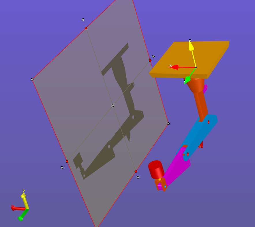
When a section plane is enabled, by default it is shown as a transparent gray rectangle. You may want to make the plane transparent in order to see the section cut more clearly.
Right-click anywhere on the section plane to open the context menu.
Click Show Section Planes.
To restore the plane, right-click anywhere in the scene background, then click Show Section Planes located at the bottom of the Workspace context menu.
Note that when the command is enabled, the corresponding icon on the context menu is highlighted.
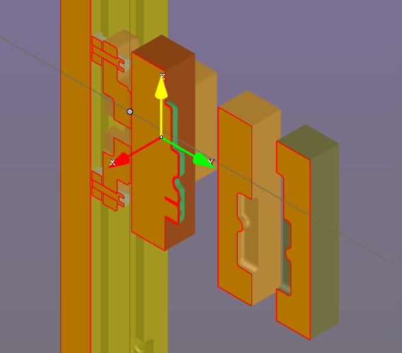
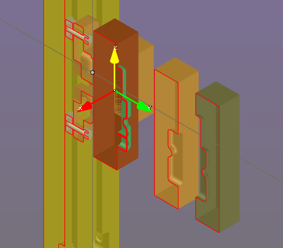
Show or hide profile edges and faces
When section a plane is enabled, by default faces and edges are both highlighted. (See Options for information about setting default colors.)
To hide highlighting:
Right-click anywhere on the section plane to open the context menu.
Click Show Profile Edges or Show Profile Faces.
To restore the highlighting, repeat the steps above.
Note that when the command is enabled, the corresponding icon on the context menu is highlighted.
Note
If you would like to see just the profile edges and no geometry, use the Cross-Section option under Standard Views on the View browser pane.
Show or hide cross-sectioning of parts and subassemblies.
By default, cross-sectioning affects every part of an assembly. However, you can choose to show or hide cross-sectioning for each of the parts and subassemblies in your model.
You must have a cross-section plane enabled before you can enable or disable cross-sectioning for objects in an assembly.
In the Assembly pane, right-click the name of the part, subassembly, or assembly for which you would like to disable or enable cross-sectioning. This opens an assembly context menu.
Point to Section to see the flyout menu.
Click Cut Material. By default, the Cut Material command is checked when cross-sectioning is enabled for the object.
Change default colors used for profile faces and edges
Click Define... to open the Define Section dialog box (Settings tab).
Click the PROFILE EDGES COLOR or PROFILE FACES COLOR button and select a color.
Click Apply to preview. Click OK to save the change.
Create...
The Align and Place By submenus offer you several options for creating and defining a cross section plane.
Create a standard cross-section plane
Open the Section menu. (Click the down-arrow to the right of the section icon on the 3D Document Toolbar.)
Click Align.
Click either XY Plane, XZ Plane, or YZ Plane. The red dots on the model designate available vertices on the model. A cross-hatch appears when the pointer is properly positioned over a vertex point.
Click a point on the model to position the plane.
Create a cross-section using three points
Open the Section menu. (Click the down-arrow to the right of the section icon on the 3D Document Toolbar.)
Point to Place By.
Click 3 Points. The red dots on the model designate available points on the model. A cross-hatch appears when the pointer is properly positioned over a point.
Click three points on the model to position the plane.
Points may not be collinear.
Create a cross-section using two points
Open the Section menu. (Click the down-arrow to the right of the section icon on the 3D Document Toolbar.)
Point to Place By.
Click 2 Points. The red dots on the model designate available points on the model.
Click two points on the model to position the plane.
Create a cross-section using two screen points
Open the Section menu. (Click the down-arrow to the right of the section icon on the 3D Document Toolbar.)
Point to Place By.
Click 2 Screen Points.
Click two points in the viewport to position the plane.
Position...
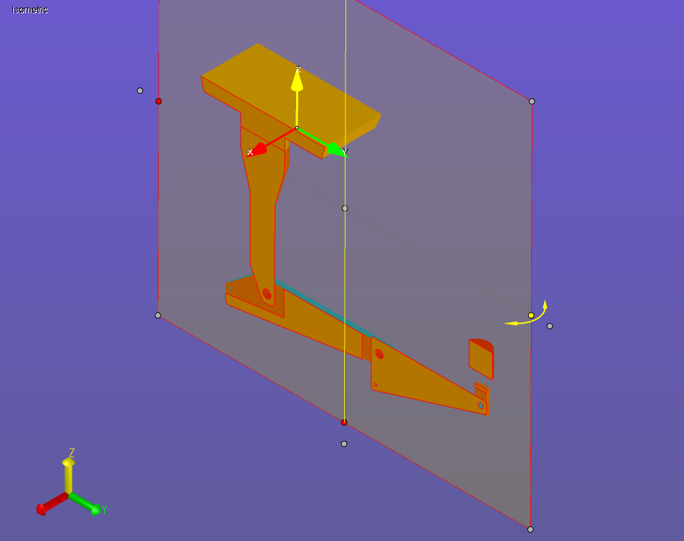
Using grips to move a plane
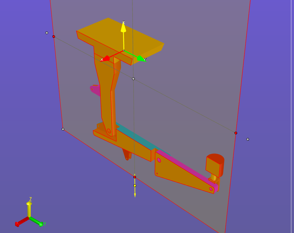
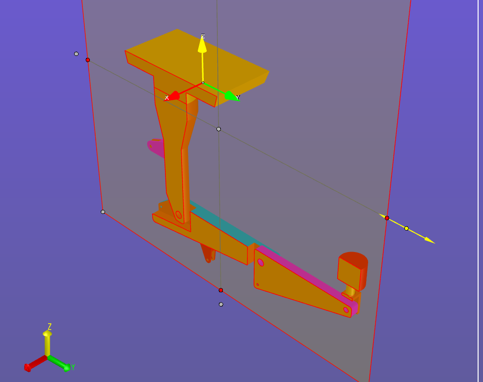
To slide the plane along a plane axis, click and drag one of the white grippers slightly offset from the center of each edge. Yellow direction arrows appear indicating in which direction you can move the plane.
To rotate the plane around a horizontal or vertical axis, click and drag one of the red grippers located in the center of each edge. Yellow direction arrows appear indicating in which direction you can move the plane.
To slide the plane along the normal axis, click and drag one of the white grippers located in the center of the plane and at each corner. Yellow direction arrows appear indicating in which direction you can move the plane.
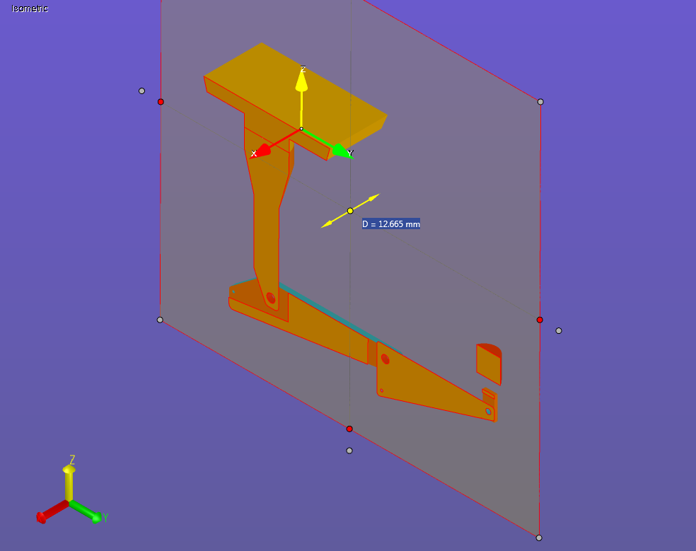
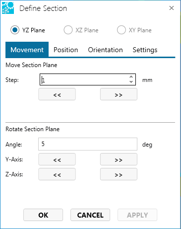
Move a section plane in increments
Move the section plane
Open the Section menu. (Click the down-arrow to the right of the section icon on the 3D Document Toolbar.)
Click Define...
Select the Movement tab on the Define Section dialog box.
In the Step field, enter the number of units you would like the plane to move each time a direction button (<< and >>) is clicked.
Use the << and >> buttons to move the plane.
Click Apply to see the effect of the movement.
Click OK to save the results and close the dialog box.
Rotate the section plane
Open the Section menu. (Click the down-arrow to the right of the section icon on the 3D Document Toolbar.)
Click Define...
Select the Movement tab on the Define Section dialog box.
In the Angle field, enter the number of degrees you would like the plane to rotate each time a direction button (<< and >>) is clicked.
Use the << and >> buttons to rotate the plane around the Y-Axis and/or the Z-Axis.
Click Apply to see the effect of the movement.
Click OK to save the results and close the dialog box.
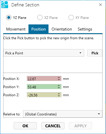
Position a section plane
From the Define Section dialog box, you can specify the point at which the plane will intersect.
Open the Section menu. (Click the down-arrow to the right of the section icon on the 3D Document Toolbar.)
Click Define...
Select the Position tab on the Define Section dialog box.
Choose one of the following methods to position a plane:
Pick a point or coordinate system:
From the drop-down menu, choose a method for selecting an element. The available methods are:
Pick a Point - Select a point on the model. Pick a Coordinate System - Select a coordinate system in the scene. The intersection point will be the origin point of the coordinate system frame.
Click the Pick button.
Select a point on the model or select a coordinate system.
Click OK to save the position and close the dialog box.
or
Enter coordinates:
Enter the coordinates of the point in the X, Y, and Z fields. This point is defined with respect to the selected coordinate system—in this case, the Global Coordinate System.
Click Apply to see the effect of the repositioning.
Click OK to save the position and close the dialog box.
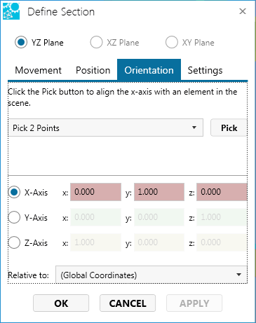
Orient a section plane
Open the Section menu. (Click the down-arrow to the right of the section icon on the 3D Document Toolbar.)
Click Define...
Select the Orientation tab on the Define Section dialog box.
Choose one of the following methods to align the plane:
Pick an element:
From the drop-down menu, choose a method for selecting an element. The available methods are:
Pick 2 Points - Select two points on the model. Pick 3 Points (Normal Plane) - Select three points on the model. Pick an Edge - Select an edge on the model. Pick a coordinate system axis - Select a coordinate system axis in the scene. The plane will align along the selected axis.
Click the Pick button.
Select points or an edge on the model or select a coordinate system axis.
Click OK to save the position and close the dialog box.
or
Enter coordinates:
Choose an axis by clicking the X-, Y-, or Z-Axis radio button.
Enter the coordinates of the point in the x, y, and z fields. This point is defined with respect to the selected coordinate system—in this case, the Global Coordinate System.
Click Apply to see the effect of the alignment.
Click OK to save the position and close the dialog box.
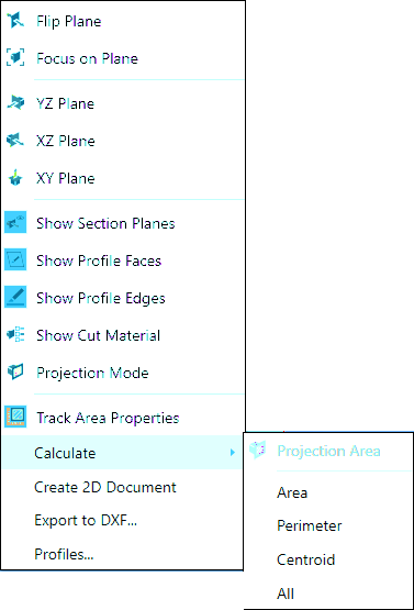
Projection and calculations...
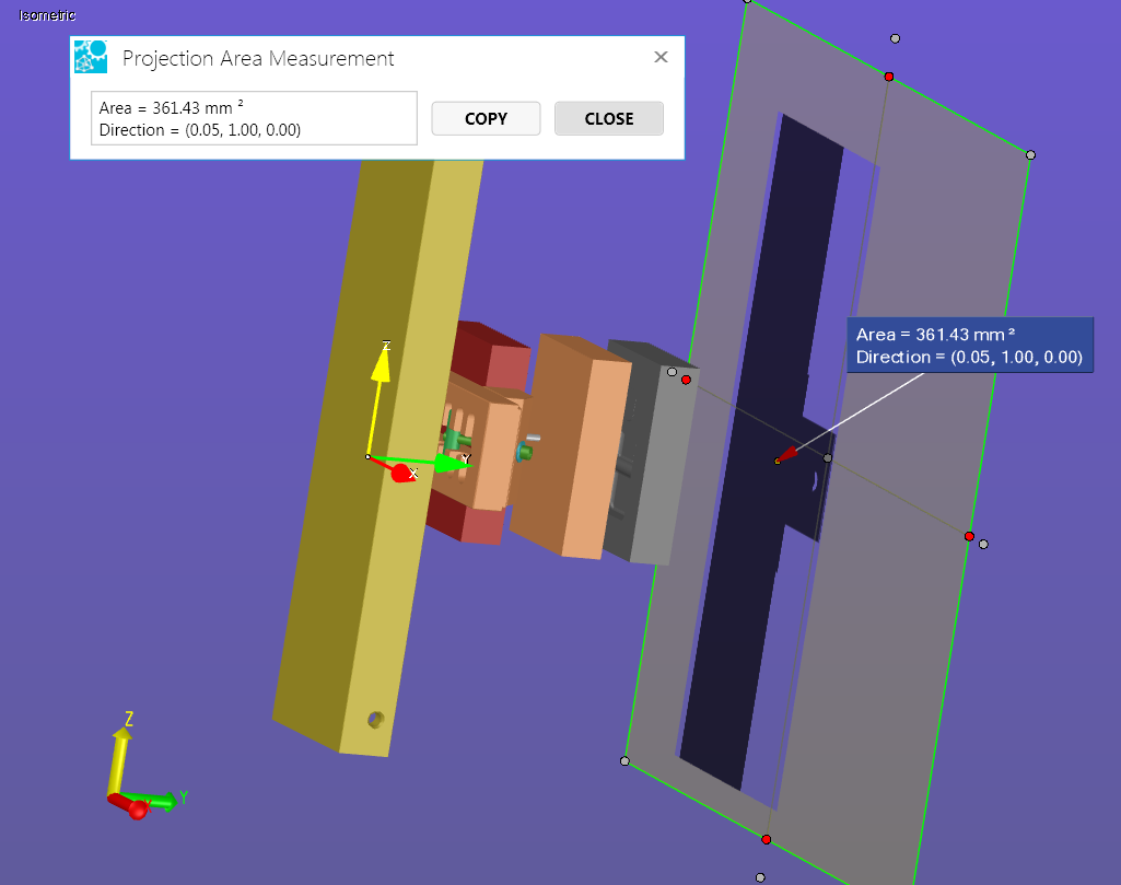
Projection Mode
To enable/disable a parallel projection plane:
Enable sectioning.
Right-click anywhere on the cross section, then select the Projection Mode option from the context menu. (Note that you may have to rotate the section plane in order to see the projection.
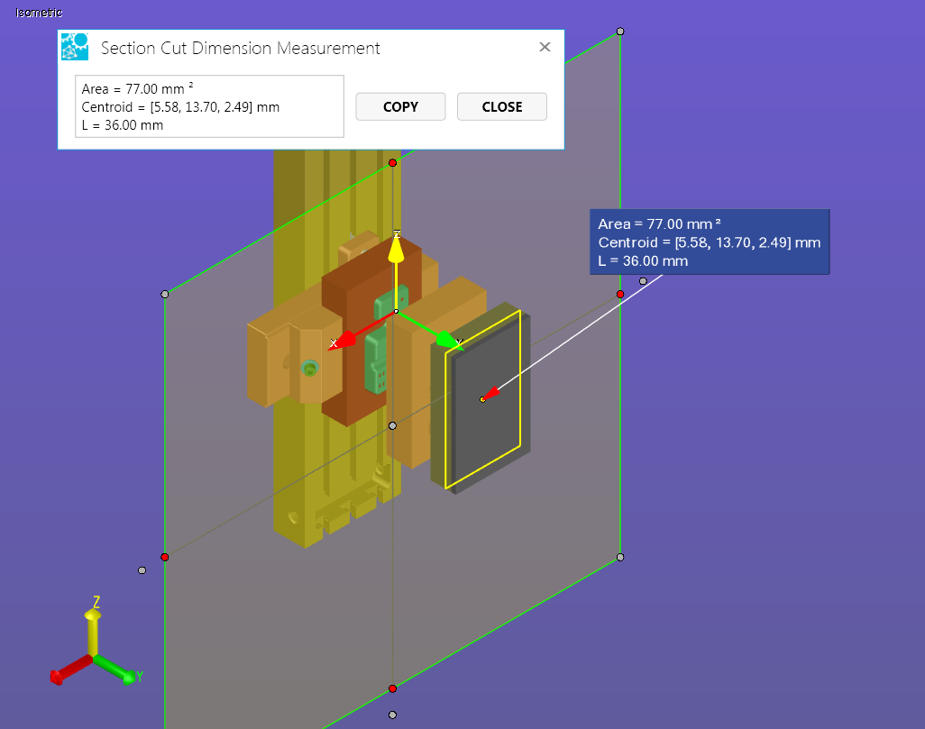
Calculations
Follow the steps below to determine the area, perimeter length, or center point of a cut or the projection area (if Projection Mode is enabled).
From the 3D Document Toolbar, click the down arrow next to the active section icon (e.g., ) to view the Section menu.
Mouse over the Calculate selection, and make a selection from the flyout menu. (Projection Area is active only if Projection Mode is enabled.)
JavaScript errors detected
Please note, these errors can depend on your browser setup.
If this problem persists, please contact our support.