3D Document Toolbar

SpinFire Ultimate opens .3D files and all 3D CAD files in 3D mode and displays the 3D document toolbar. With this toolbar, you can initiate commands using a combination of buttons and menus to view and manipulate document objects.
Open a menu by clicking the drop-down arrow to the right of an icon on the toolbar. Once you have used a particular command, the icon associated with that command will remain on the toolbar. You can then quickly repeat the last command you called with just one click.
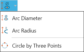
For example, to measure the diameter of an arc, click the drop-down arrow next to the current Radial menu icon, then select Arc Diameter. The Arc Diameter icon will remain on the toolbar until another linear measurement command is selected.
To find out which command is active, move your pointer over the icon to see the pop-up label.
 | ||
| ||
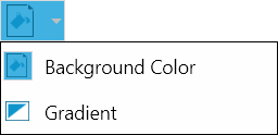
| Enables you to override the default Workspace background color and gradient options (see 3D Viewer Settings).
| |
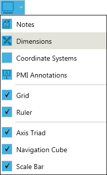
 | Controls whether or not notes, dimensions, coordinate systems, or PMI annotations are displayed in the scene. You can also use this menu to turn on/off the grid, axis triad, or navigation cube.
Also see Scale Bar. | |
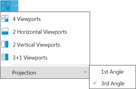
 | Contains options for splitting the viewport into two or more viewports. See Controlling the View for details
| |
 | ||
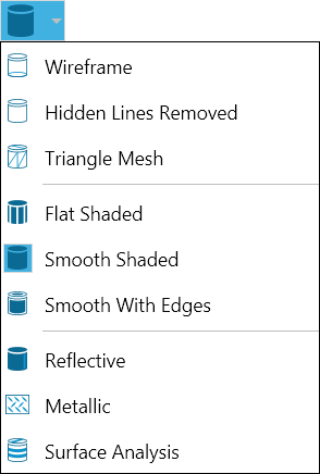
 | Controls how the 3D objects are drawn (the default is set on the 3D Viewer Settings page). See also Assemblies and Parts in a 3D Scene.
| |
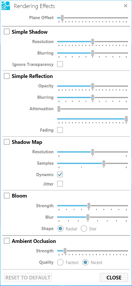
 | Controls resolution, blurring, and intensity of blooms (bright spots), reflections, and shadows. (Defaults are set on the 3D Viewer Settings page.)
| |
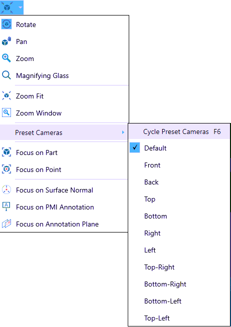
 | Contains mouse mode (pointer behavior) and viewing options. See Controlling the View for details.
| |
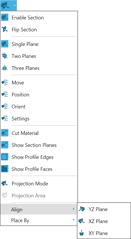
 | Contains section plane and profile display commands; controls profile colors and plane alignment and placement. See Cross-Sectioning a 3D Model for details.
|


 | Contains commands for inserting a note markup label. See /wiki/spaces/SF1100/pages/2785854224 and 3D Notes for details.
| |
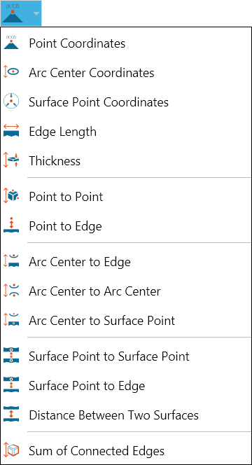
 | Contains commands for measuring lengths, coordinates, and edges. See 3D Dimensions and 3D Linear Menu for details.
| |
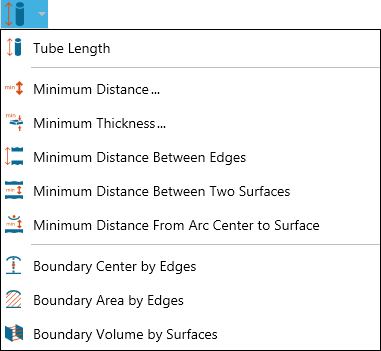
 | Contains commands for measuring lengths, minimum thickness and distances, and areas. See 3D Dimensions and 3D Linear Menu for details.
| |
 | Contains commands for measuring arcs and circles. See 3D Dimensions and 3D Radial Menu for details.
| |
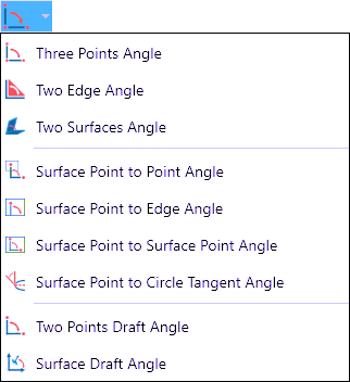
 | Contains commands for measuring angles. See 3D Dimensions and 3D Angular Menu for details.
| |
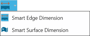
 | A versatile edge and surface measuring tool. See Smart Dimensions for details.
| |
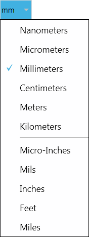
 | Provides options for choosing length measurement units. The new selection will override the default settings only in the active viewport. See Options.
| |
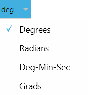
 | Lists options for choosing angle measurement units. The new selection will override the default settings only in the active viewport. See Options. | |
 | Lists options for choosing weight measurement units. The new selection will override the default settings only in the active viewport. See Options. | |
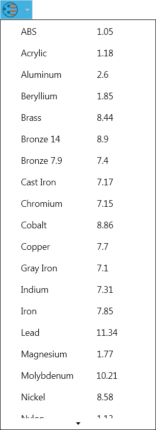
 | Provides options for choosing which material is to be used when the object is manufactured. The drop-down list originates from the Measurement section on the 3D Viewer settings page > Define Materials.... The new selection will override the default settings only in the active viewport. See Options. | |
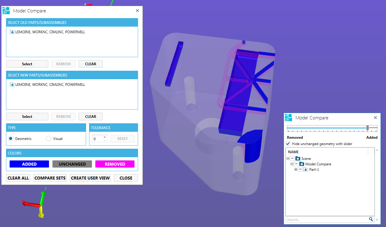
 | Perform further analysis on your model with color mapped visuals with model compare, draft angle analysis, wall thickness and curvature. The Model Compare functionality takes two similar parts and displays what is the same and different through the use of coloring the parts.
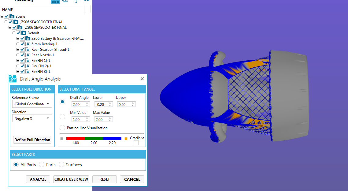
See Model Compare. The Draft Angle Analysis allows the user to easily analyze a part for proper draft angle. A Draft Angle describes the amount of taper for molded or cast parts perpendicular to the parting line.
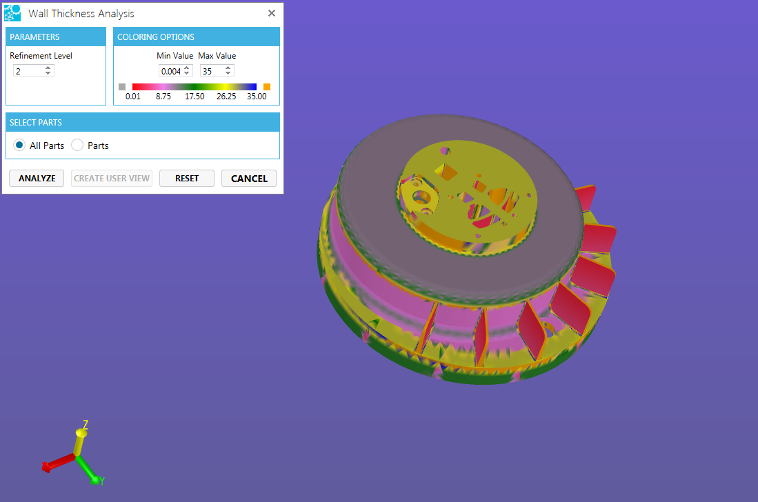
See Draft Angle Analysis. Discovery changes in thickness of parts using the Wall Thickness Analysis tool. One can quickly determine if parts are too thick or too thin with the color washing of the model.
Curvature analysis color maps the curvature of a surface based on the curvature analysis used (Gaussian, Mean, Maximum) to aid in design and manufacturing preparation.
See Curvature Analysis. | |
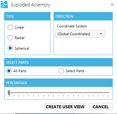
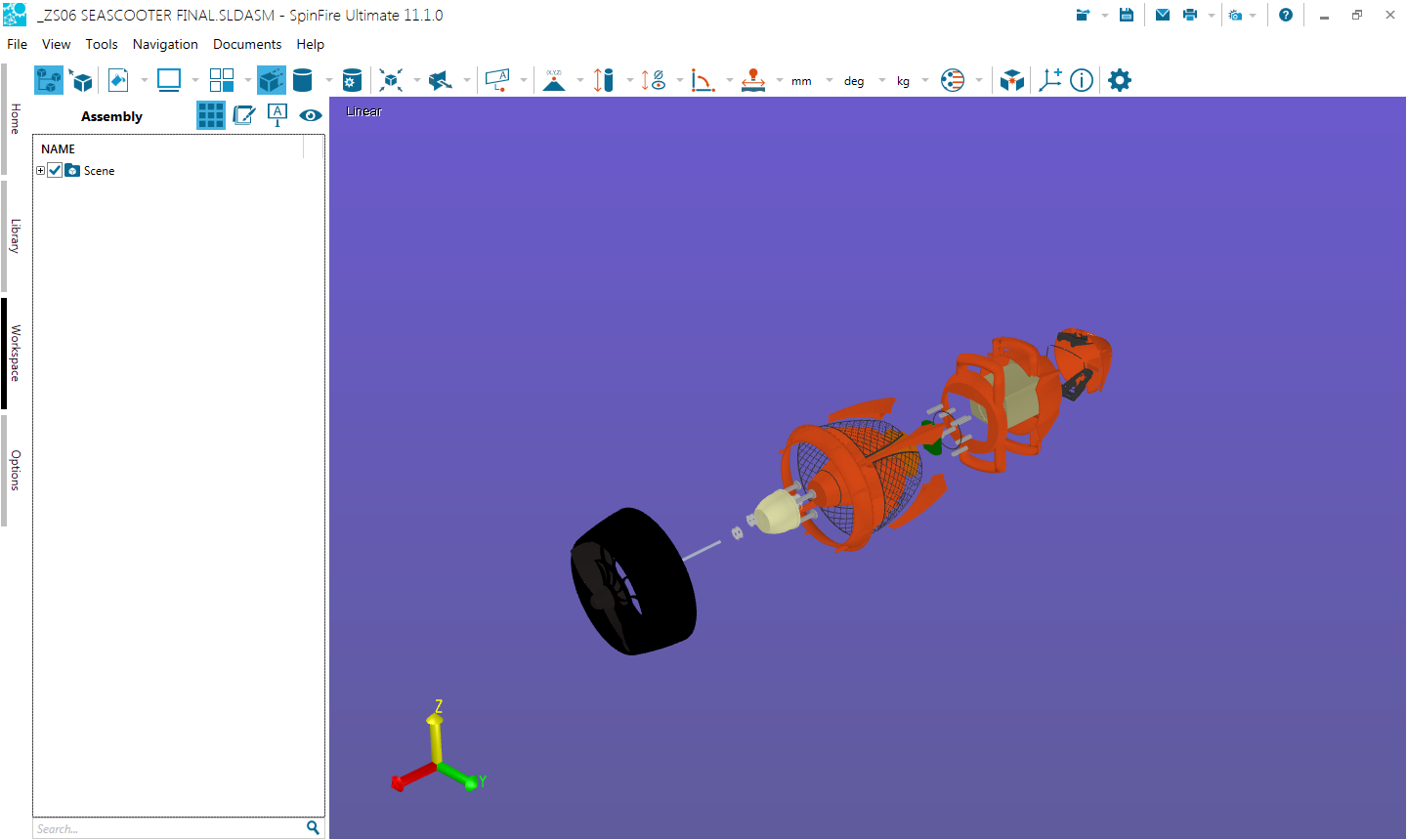
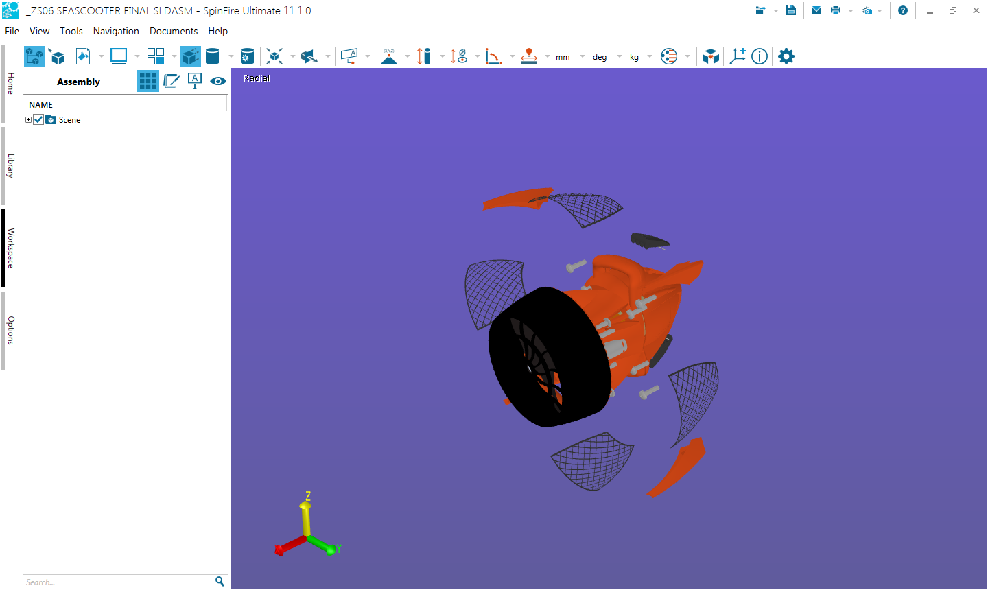
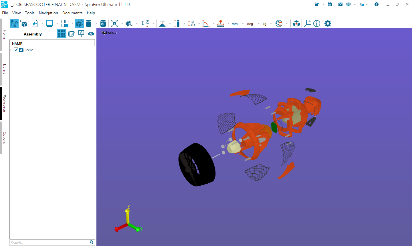
 | Exploded Assembly enables you to quickly transform multiple or all parts of an assembly in a chosen uniform pattern. Choose one of the three different transformation methods:
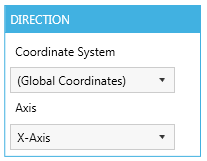
Linear - Transforms the parts of the assembly in a straight line along the selected axis. Radial - Transforms the parts of the assembly in a circular direction around the selected axis, starting from the coordinate system origin. Spherical - Transforms the parts of the assembly in a spherical direction around the coordinate system origin.
Select the entire assembly or selected parts o perform the assembly explode.
Slider Bar - Use the percentage slider bar (0-100) to view the assembly exploding in real-time.
Click the Create User View button to save the exploded assembly transformation. Clicking Cancel, to return to the original model view. | |
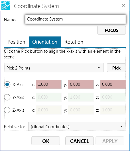
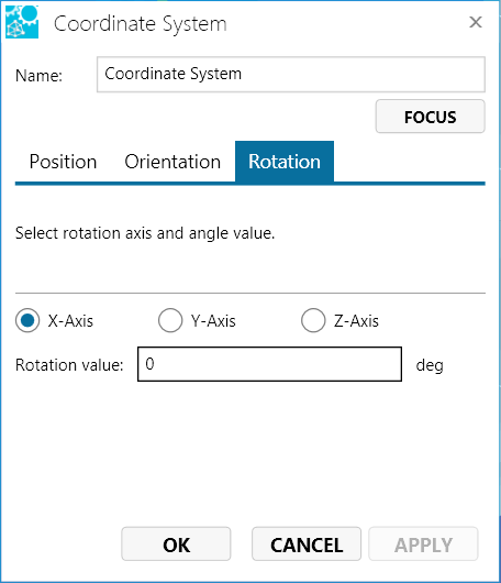
| Opens a dialog box for creating/changing a coordinate system. See Coordinate Systems in a 3D Scene for details.
| |
 | Shows the meta data found in the CAD file.
For parts, users can enter in additional data to be saved with their ACT3D files.
| |
| ||
| ||
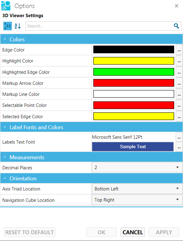
 | Opens an Options dialog box that allows you to change 3D Viewer settings.
| |
|