
Working with 2D Documents
Linear Measurements
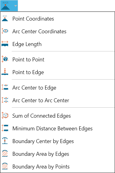
- Click the Smart Edge Dimension icon on the 2D Document Toolbar.

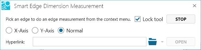
- Mouse over and select a highlighted edge.
- Optional:
- Select Lock tool to use the command more than once.
- Enter a hyperlink to a file or to a document and user view within the current file.
- Position your cursor on an edge. (Selectable edges are highlighted when you mouse over them.)
- Double-click the left mouse button to measure the edge length (default).
- Or click the right mouse button to bring up a context menu containing additional measurement options, then make your selection.

If the edge you select is an arc, the context menu will contain more measurement choices.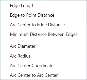
- Drag and click to position the label in the scene.
Radial Measurements

Angular Measurements
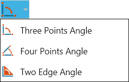
- Open the Angular menu on the 2D Document Toolbar. (Click the drop-down arrow to the right of the Linear icon to see the menu of commands.)
- Select Three Points Angle.
- Optional:
- Select Lock tool to use the command more than once.
- Enter a hyperlink to a file or to a document and user view within the current file.
- Position your cursor on the first point and click. (Crosshairs appear when you mouse over a selectable point.) The selected point is yellow.
- Select the second and third points. The second point will be the vertex point of the angle.
- Drag and click to position the markup in the drawing.
- Optional: Click Copy to copy the markup content to the Windows clipboard.
- Click Stop when you're finished taking multiple measurements. Click Close (or X) to end the command and close the dialog box.
Note
Once the markup label is displayed, you can also determine the reflex angle by using the Flip Axis command on the markup context menu. See Working with 2D Markups for information on using this command and the context menu.
- Open the Angular menu on the 2D Document Toolbar. (Click the drop-down arrow to the right of the Linear icon to see the menu of commands.)
- Select Four Points Angle.
- Optional:
- Select Lock tool to use the command more than once.
- Enter a hyperlink to a file or to a document and user view within the current file.
- Position your cursor on the first point and click, then select the second point. (Crosshairs appear when you mouse over a selectable point. A selected point is yellow). These two selections define the first side of the angle.
- Select the third and fourth points. These selections define the second side of the angle, which SpinFire extends to intersect with the first side.
- Drag and click to position the markup in the drawing.
- Optional: Click Copy to copy the markup content to the Windows clipboard.
- Click Stop when you're finished taking multiple measurements. Click Close (or X) to end the command and close the dialog box.
Note
Once the markup label is displayed, you can also determine the reflex angle by using the Flip Axis command on the markup context menu. See Working with 2D Markups for information on using this command and the context menu.
- Open the Angular menu on the 2D Document Toolbar. (Click the drop-down arrow to the right of the Linear icon to see the menu of commands.)
- Select Two Edge Angle.
- Optional:
- Select Lock tool to use the command more than once.
- Enter a hyperlink to a file or to a document and user view within the current file.
- Position your cursor on the first edge and click. (Selectable edges are highlighted when you mouse over them.)
- Select the second edge.
- Drag and click to position the markup in the drawing.
- Optional: Click Copy to copy the markup content to the Windows clipboard.
- Click Stop when you're finished taking multiple measurements. Click Close (or X) to end the command and close the dialog box.
Note
Once the markup label is displayed, you can also determine the reflex angle by using the Flip Axis command on the markup context menu. See Working with 2D Markups for information on using this command and the context menu.
Notes
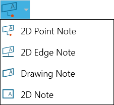
- Open the Notes menu on the 2D Document Toolbar. (Click the drop-down arrow to the right of the Notes icon to see the menu of commands.)
- Click 2D Point Note. Mouse over your drawing. Highlighted edges designate where there are available points on the model. Crosshairs indicate the point where the label will attach.
- When the label appears, drag it into position with your pointer.
- Click once to set the position of the label. A cursor will appear in the label.
- Type the text of your label and press Enter.
Note
If you want to add several of the same type of markup, you may select the Lock tool check box that appears when you select a markup command. This will allow you to keep adding the same type of markup to the scene until you click Stop- Open the Notes menu on the 2D Document Toolbar. (Click the drop-down arrow to the right of the Notes icon to see the menu of commands.)
- Click 2D Edge Note.
- Click the edge you wish to label. The edge is highlighted when the pointer is properly positioned.
- When the label appears, drag it into position with your pointer.
- Click once to set the position of the label. A cursor will appear in the label.
- Type the text of your label and press Enter.
Note
If you want to add several of the same type of markup, you may select the Lock tool check box that appears when you select a markup command. This will allow you to keep adding the same type of markup to the scene until you click Stop.- Open the Notes menu on the 2D Document Toolbar. (Click the drop-down arrow to the right of the Notes icon to see the menu of commands.)
- Click Drawing Note. The label will appear.
- Drag the label into position with your pointer.
- Click once to set the position of the label. A cursor will appear in the label.
- Type the text of your label and press Enter.
Note
If you want to add several of the same type of markup, you may select the Lock tool check box that appears when you select a markup command. This will allow you to keep adding the same type of markup to the scene until you click Stop.- Open the Notes menu on the 2D Document Toolbar. (Click the drop-down arrow to the right of the Notes icon to see the menu of commands.)
- Click 2D Note. The label will appear.
- Drag the label into position with your pointer.
- Click once to set the position of the label. A cursor will appear in the label.
- Type the text of your label and press Enter.
Note
If you want to add several of the same type of markup, you may select the Lock tool check box that appears when you select a markup command. This will allow you to keep adding the same type of markup to the scene until you click Stop.Overriding default settings from the toolbar
Changes made from the 2D Document Toolbar effect the appearance of notes and markups for the active document only and do not change the appearance of markups that already exist in the scene. If you want to change the appearance of existing markups, see Working with 2D Markups.
- Open the Length Units menu on the 2D Document Toolbar. (Click the drop-down arrow to the right of the Length Units icon to see the unit list.)
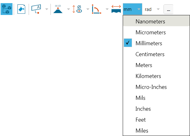
- Make your selection.
- Open the Angular Units menu on the 2D Document Toolbar. (Click the drop-down arrow to the right of the Angular Units icon to see the unit list.)
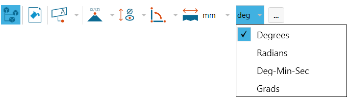
- Make your selection.
- On the 2D Document Toolbar, click the Settings icon.

- In the Options dialog box, click the appropriate COLOR… button.

- In the Color dialog box, choose from Standard Colors or Recent Colors or create a new custom color.
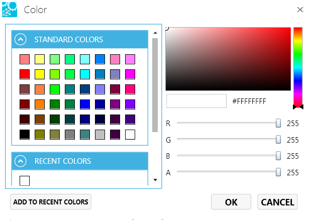
- Click OK.
To revert color changes back to default settings:
- On the 2D Document Toolbar, click the Settings icon again.
- In the Options dialog box, click the RESET TO DEFAULT button.
- On the 2D Document Toolbar, click the Settings icon.
- In the Options dialog box, click the font name in the Label Fonts and Colors field.
- In the Font dialog box, choose a new font, style, size, color, and/or effects.
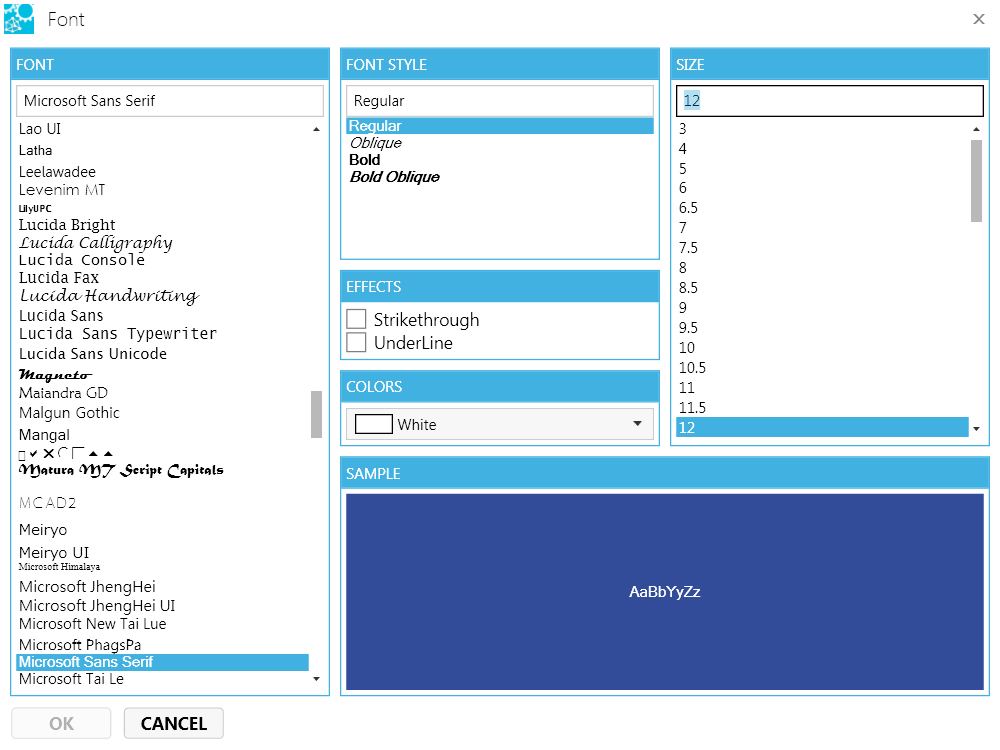
- Click OK.
- In the 2D Document Toolbar, click the Background Color icon.

- In the Color dialog box, choose from Standard Colors or Recent Colors or create a new custom color.
- Click the OK button.
Using the browsers
- Click the Markups icon on the 2D Browser Toolbar.

- Clear/select the note or markup checkbox to hide/show the label.

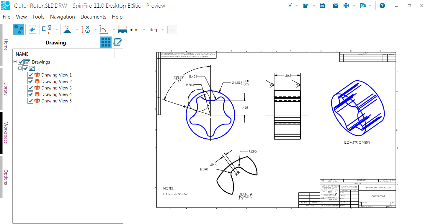
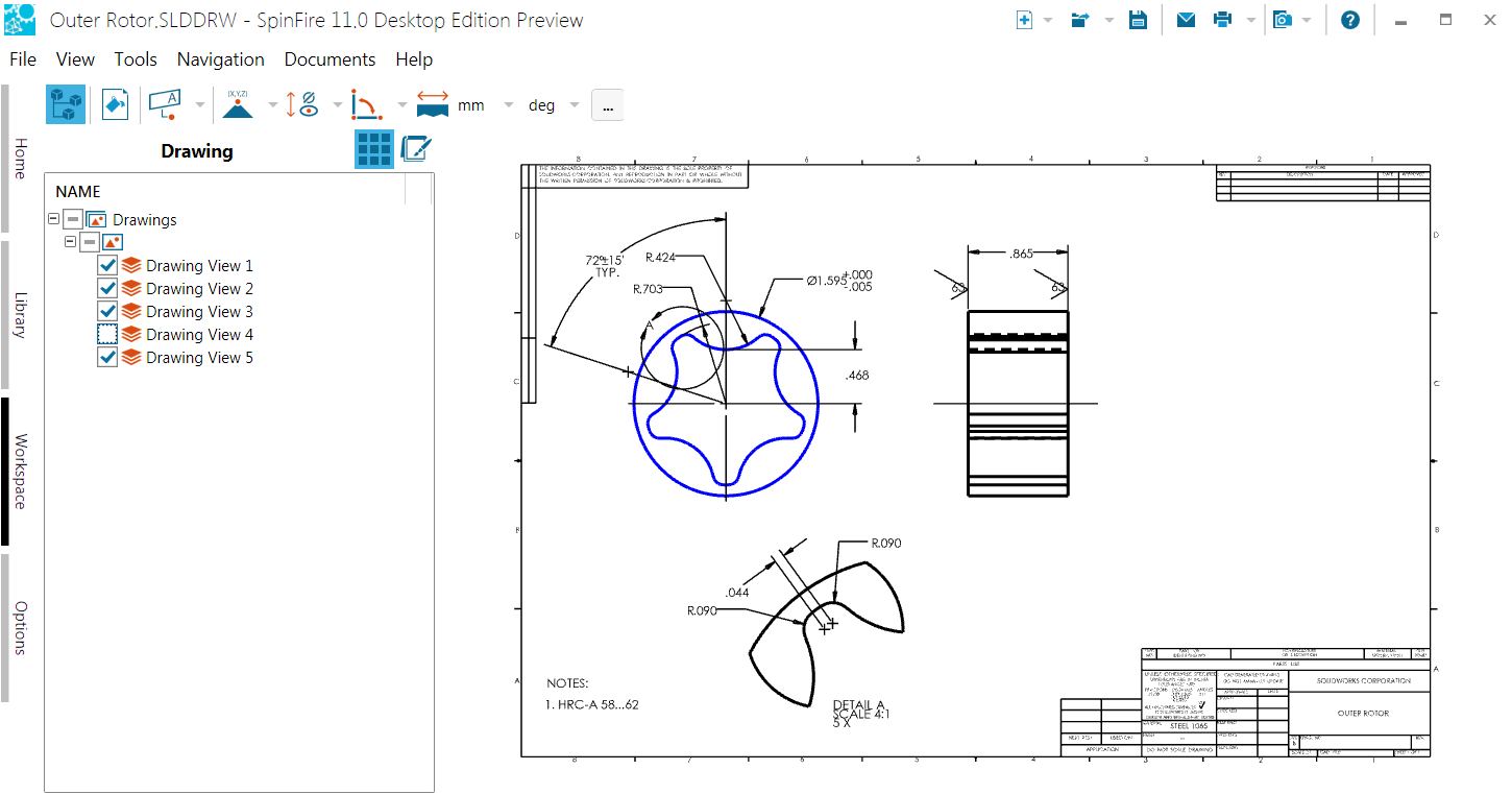
- Click the Drawing icon on the 2D Browser Toolbar.

- Clear/select the node or layer checkbox to hide/show the object in the drawing.
2D Markups
2D Drawings
- Right-click the drawing under "Drawings, such as "Sheet", or "Model"
- Select Transform
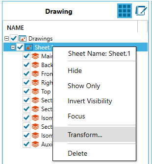
- Select either
- Move
- Rotate
- Scale
- Key in the values
- Select Apply
