Advanced Measurements
Measure tube length
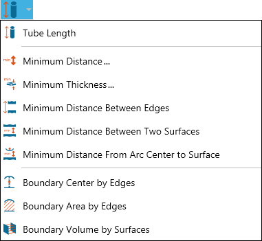
- Open the Advanced Measurements menu on the 3D Document Toolbar. (Click the drop-down arrow to the right of the Linear icon to see the menu of commands.)
- Select Tube Length.
- Optional:
- Select Lock tool to use the command more than once.
- Enter a hyperlink to a file or to a document and user view within the current file.
- Check Auto Complete to have SpinFire Ultimate attempt to find the end of the tube. Uncheck to manually select the path of arcs to the end of the tube.
- Position your cursor on the starting arc or circle and click. (Selectable arcs and circles are highlighted as you mouse over them.) The selected arc or circle remains highlighted.
- In non-Auto Complete mode, continue to click arcs or circles that define the tube. A green line traversing the center of the tube indicates what will be measured.
- Double-click the last arc or circle to end the sequence.
- Drag the label into position and click once.
- Optional:
- Click Copy to copy the markup content to the Windows clipboard.
- Click Export... to save the tube length bill of materials (BOM) into a file (.txt, .csv, .xml, .xls, .xlsx).
- Click Stop when you're finished taking multiple measurements. Click Close (or X) to end the command and close the dialog box.
Note
Recommendation: To find arcs and circles more easily, select your model and render as Smooth with Edges. See also Measurement Tips.
Measure the minimum distance between sets of parts/surfaces
- Open the Advanced Measurements menu on the 3D Document Toolbar. (Click the drop-down arrow to the right of the Linear icon to see the menu of commands.)
- Select Minimum Distance....
- Choose the type of object(s) you are measuring: Parts (default) or Surfaces.
- To create SET #1:
- Click the part or parts (or surfaces) on the model.
- When you have finished selecting, click the Stop Selection button.
- To create SET #2:
- Click the SET #2 Select button, then the part or parts (or surfaces) on the model.
- When you have finished selecting, click the Stop Selection button.
- Click the CALCULATE button to display the measurement label.
- Drag the label into position and click.
- To measure the distance between another set of objects, click the CLEAR ALL button, then click the SET #1 Select button. Repeat steps 3 to 7.
Measure the minimum thickness of parts/surfaces
- Open the Advanced Measurements menu on the 3D Document Toolbar. (Click the drop-down arrow to the right of the Linear icon to see the menu of commands.)
- Select Minimum Thickness....
- Choose the type of object(s) you are measuring: Parts (default) or surfaces.
- To create your set of objects, click the part or parts (or surfaces) on the model. When you have finished selecting, click the Stop Selection button.
- Under Parameters, select Draft Angel and Modeling Tolerance values.
- Click the CALCULATE button to display the measurement label.
- Drag the label into position and click once.
Note
You can add to your set of objects by clicking the Select button again.
Measure the minimum distance between edges
- Open the Advanced Measurements menu on the 3D Document Toolbar. (Click the drop-down arrow to the right of the Linear icon to see the menu of commands.)
- Select Minimum Distance Between Edges.
- Optional:
- Select Lock tool to use the command more than once.
- Click a radio button to select a measurement axis (the default is Normal).
- Enter a hyperlink to a file or to a document and user view within the current file.
- Position your cursor on an edge and click. (Selectable edges are highlighted.) A selected edge remains highlighted.
- Select the second edge.
- The selected edges appear in yellow. Drag and click to position the markup in the scene.
- Optional: Click Copy to copy the markup content to the Windows clipboard.
- Click Stop when you're finished taking multiple measurements. Click Close (or X) to end the command and close the dialog box.
Measure the minimum distance between two surfaces
- Open the Advanced Measurements menu on the 3D Document Toolbar. (Click the drop-down arrow to the right of the Linear icon to see the menu of commands.)
- Select Minimum Distance Between Two Surfaces.
- Optional:
- Select Lock tool to use the command more than once.
- Click a radio button to select a measurement axis (the default is Normal).
- Enter a hyperlink to a file or to a document and user view within the current file.
- Position your cursor on a surface and click. (Selectable surfaces are highlighted.)
- Select the second surface.
- Drag and click to position the markup in the scene.
- Optional: Click Copy to copy the markup content to the Windows clipboard.
- Click Stop when you're finished taking multiple measurements. Click Close (or X) to end the command and close the dialog box.
Measure the minimum distance from an arc center to a surface
- Open the Advanced Measurements menu on the 3D Document Toolbar. (Click the drop-down arrow to the right of the Linear icon to see the menu of commands.)
- Select Minimum Distance From Arc Center to Surface.
- Optional:
- Select Lock tool to use the command more than once.
- Click a radio button to select a measurement axis (the default is Normal).
- Enter a hyperlink to a file or to a document and user view within the current file.
- Position your cursor on an arc and click. (Selectable arcs are highlighted as you mouse over them.)
- Position your cursor on a surface and click. (Selectable surfaces are highlighted.)
- Drag and click to position the markup in the scene.
- Optional: Click Copy to copy the markup content to the Windows clipboard.
- Click Stop when you're finished taking multiple measurements. Click Close (or X) to end the command and close the dialog box.
Calculate boundary center by edges
- Open the Advanced Measurements menu on the 3D Document Toolbar. (Click the drop-down arrow to the right of the Linear icon to see the menu of commands.)
- Select Boundary Center by Edges.
- Optional:
- Select Lock tool to use the command more than once.
- Enter a hyperlink to a file or to a document and user view within the current file.
- Position your cursor on an edge and click. (Selectable edges are highlighted as you mouse over them.) A selected edge remains highlighted.
- Continue selecting connected edges until SpinFire determines the intended boundary shape and calculates its center point.
- The boundary center point appears in yellow. Drag and click to position the markup in the scene.
- Optional: Click Copy to copy the markup content to the Windows clipboard.
- Click Stop when you're finished taking multiple measurements. Click Close (or X) to end the command and close the dialog box.
Calculate an area by boundary edges
- Open the Advanced Measurements menu on the 3D Document Toolbar. (Click the drop-down arrow to the right of the Linear icon to see the menu of commands.)
- Select Boundary Area by Edges.
- Optional:
- Select Lock tool to use the command more than once.
- Enter a hyperlink to a file or to a document and user view within the current file.
- Position your cursor on an edge and click. (Selectable edges are highlighted as you mouse over them.) A selected edge remains highlighted.
- Continue selecting connected edges until SpinFire determines the intended boundary shape and calculates its area.
- The boundary area appears as a highlighted surface. You can hide this surface by right-clicking the markup and choosing Hide Surface from the context menu.
- Drag and click to position the markup in the scene.
- Optional: Click Copy to copy the markup content to the Windows clipboard.
- Click Stop when you're finished taking multiple measurements. Click Close (or X) to end the command and close the dialog box.
Calculate the volume of a space using surfaces
- Open the Advanced Measurements menu on the 3D Document Toolbar. (Click the drop-down arrow to the right of the Tube Length icon to see the menu of commands.)
- Select Boundary Volume by Surfaces.
- Optional:
- Select Lock tool to use the command more than once.
- Enter a hyperlink to a file or to a document and user view within the current file.
- Position your cursor on a surface and click. (Selectable surfaces are highlighted as you mouse over them.) A selected surface remains highlighted.
- Continue selecting surfaces until you have defined the space; double-click the last surface to end selection.
- Drag and click to position the markup in the scene.
- Optional: Click Copy to copy the markup content to the Windows clipboard.
- Click Stop when you're finished taking multiple measurements. Click Close (or X) to end the command and close the dialog box.