
Working with Views
Zoom, pan, and rotate
Rotate is the default setting when a 3D document is opened. Simply click on the model and drag with your pointing device.
If the Rotate icon is not visible on the toolbar,
- Right-click on the scene background, then select Rotate.
or
- On the 3D Document toolbar, click on the down arrow located next to the current Zoom menu icon, then select Rotate.
Note
This operation rotates your view of the model, not the actual assembly or drawing. To rotate a 3D assembly itself, see Assemblies and Parts in a 3D Scene.
- Right-click anywhere in the background of the scene to open the Zoom menu.
- Select Zoom.
- Left-click+Drag up to zoom out, down to zoom in.
If you have a wheel mouse, you can zoom in/out by clicking in the viewport and rotating the wheel.
Note
You can also access the Zoom command from the 3D Document toolbar.
- Right-click anywhere in the background of the scene to open the Zoom menu.
- Select Zoom Window.
- Drag across the area you would like to zoom in on. A rectangle shows the boundries of the area you are selecting.
- Release the mouse button.The area you selected will fill your view.
Note
You can also access the Zoom Window command from the 3D Document toolbar.
- When sectioning is enabled, right-click anywhere in the background of the scene to open the Zoom menu.
- Select Move Section.
- Hold the left mouse button down and drag the section plane to the desire location along its axis.
- Release the mouse button.
Note
You can also access the Move Section command from the 3D Document toolbar.
3D zoom and focus
- Right-click anywhere in the background of the scene to open the Zoom menu.
- Select Zoom Fit. SpinFire Ultimate will pan and zoom to fit the document contents entirely within the viewport.
Note
You can also access the Zoom Fit command from the 3D Document toolbar.
- Right-click anywhere in the background of the scene to open the Zoom menu.
- Select Focus on Part.
- Click on a part.
- SpinFire will zoom in on that part.
Note
You can also access the Focus on Part command from the 3D Document toolbar.
- Right-click anywhere in the background of the scene to open the Zoom menu.
- Select Focus on Point.
- Click on a part.
- SpinFire will pan the scene until selected point is in the center of the viewport.
Note
You can also access the Focus on Point command from the 3D Document toolbar.
- Right-click anywhere in the background of the scene to open the Zoom menu.
- Select Focus on Surface Normal.
- Hover the mouse over a part with the surface normal indicator.
- Click on the part.
- SpinFire moves the scene camera to view the part down at the surface normal point.
Note
You can also access the Focus on Surface Normal command from the 3D Document toolbar.
- Right-click anywhere in the background of the scene to open the Zoom menu.
- Select Focus on Annotation Plane.
- Hover the mouse over a part with the surface normal indicator.
- Click on a PMI annotation or annotation plane.
- SpinFire rotates the scene camera to view the part parallel with the annotation plane.
Note
You can also access the Focus on Annotation Plane command from the 3D Document toolbar.
- Right-click anywhere in the background of the scene to open the Zoom menu.
- Select Focus on PMI Annotation.
- Click on a PMI annotation.
- SpinFire sets focus on the PMI annotation rotating the camera to the same plane as the annotation.
Note
You can also access the Focus on PMI Annotation command from the 3D Document toolbar.
A scene always contains the Global Coordinate System and may contain additional coordinate systems. The Focus command positions the origin point of a coordinate system in the center of your view.
- Right-click a coordinate system. This can be done either in the Markups pane or in the scene (on the 0,0,0 point).
- Select Focus.
Note
You can also focus on a coordinate system by double-clicking the coordinate system name in the Markups pane.
The Coordinate System Properties dialog box also has a Focus command button.
3D model display
- Click the Options tab. (The Options page can also be accessed from the Navigation menu or the Home page.)
- Click the 3D Viewer tab.
- Under Views and Viewports, Projection, select 1st Angle or 3rd Angle from the drop-down menu.
- Click the Apply Settings button.
Note
You can change the projection angle for the current view by clicking the drop-down arrow next to the Viewports icon in the 3D Document toolbar, highlight Projection, and then select either 1st Angle or 3rd Angle from the flyout menu.
Click the Perspective/Parallel Mode icon on the 3D Document Toolbar.
Note
You may also choose Isometric projection from the Views browser pane by clicking Default under Standard Views.
Click the drop-down arrow next to the current rendering mode icon. For example, the current rendering mode may be Smooth Shaded, so, on the 3D Document toolbar, you would see the following:
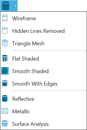
Select the new rendering mode from the menu.
To select and change rendering characteristics, click the Rendering Effects icon on the 3D Document Toolbar.
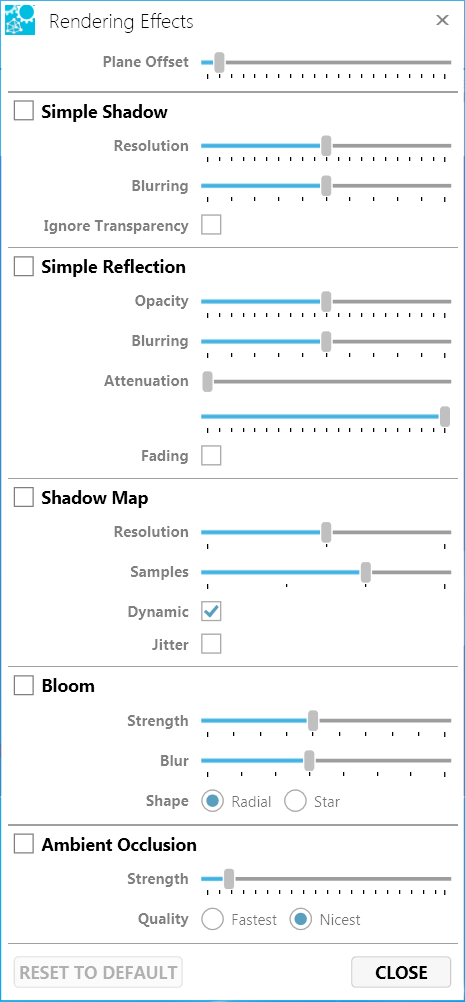
On the Rendering Effects dialog box, select or clear checkboxes.
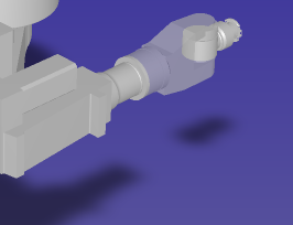
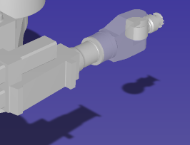
Creates a shadow cast by the model.
Resolution - Determines the sharpness and density of the shadow image.
Values are 2, 4, 8, 16, 32, 64, 128, 256, 512, 1024 ppi.
Blurring - The degree to which the shadow edges are blurred.
Values are 2, 4, 8, 16, 32, 64, 128, 256.
Ignore Transparency - If selected, any transparent parts of the object will cast a shadow.
- Click the markups icon in the browser toolbar to view the Markups browser pane.
- Clear or select the check box next to a coordinate system listed in the assembly tree.
- To hide/show all coordinate systems, clear or select the check box next to Coordinate Systems.
Note
The orientation axis types Triad and Navigation Cube—specified under Views and Viewports on the 3D Viewer Settings page—cannot be hidden. If you wish to clear all orientation axes from the view, change the setting to None.
Views
- Open the Viewports menu on the 3D Document Toolbar. (Click the drop-down arrow to the right of the viewports icon to see a drop-down menu listing the available commands.)
- Click the viewport arrangement you want.
- Optional: To resize a viewport, left-click+drag a separation border.
Note
Once you have made a selection, the viewports icon becomes a toggle, which enables you to switch back and forth between a single viewport and multiple viewports.
- Set up your view of the model (viewport, position, markups, and sectioning settings can be saved as a part of your view).
- Click the Views icon on the browser toolbar.
- Right-click User Views.
- Click New...
- Type a name for your view and click OK. Your view will appear under User Views along with your username and the time it was saved.
Note
If you don't see your saved view listed in the Views browser, double-click User Views to expand the list.
Double-click the user view name to see features saved as a part of the view (camera, geometry, sectioning, markups, and annotations).
To remove or update camera position, geometry, or section:
- Double-click the user view name.
- Right-click Camera, Geometry, or Section, then make a selection from the context menu.
To show camera position, geometry, or section:
- Right-click the user view name, then select Capture Camera, Capture Geometry, or Capture Section from the context menu.
Note
If the user view already contains camera, geometry, or section information, the corresponding capture command will be grayed out.
To remove all markups from the user view:
- Double-click the user view name.
- Right-click Markups, then select Remove All.
To add or move a markup to another user view:
- Double-click the user view name, then double-click Markups.
- Right-click the markup you want to move or add to another view.
- Select from the context menu.
Note
You cannot move or add a markup to a standard view.