
Working with Assemblies and Parts
Commands from the Assembly Context Menu
- Right-click an object in the assembly tree to open the assembly context menu (or use CTRL+click or SHIFT+click to select multiple objects, then right-click). You can also select a part or parts in the viewport: Right-click a single part; CTRL+right-click multiple parts.
- Click Show Only object name or Hide object name.
- To display all objects again, right-click Scene (at the top of the assembly tree), then select Show All Parts.
Note
A checkmark indicates that the object is displayed.
- Right-click an element in the drawing tree or in the viewport.
- Click Show Only object name or Hide object name.
Note
To hide/show the entire drawing, right-click Drawing (at the top of the drawing tree), then select Hide Drawings (or Show Drawings).
- Right-click an object in the assembly tree to open the assembly context menu (or use CTRL+click or SHIFT+click to select multiple objects, then right-click). You can also select a part or parts in the viewport: Right-click a single part; CTRL+right-click multiple parts.
- Select Color.
- Select either Front and Back..., Front..., or Back... to open the Color dialog box.

- Click a color swatch or create your own color.
- Click OK.
- Right-click an object in the assembly tree to open the assembly context menu (or use CTRL+click or SHIFT+click to select multiple objects, then right-click). You can also select a part or parts in the viewport: Right-click a single part; CTRL+right-click multiple parts.
- Select Transparency... to open the Transparency slider box.
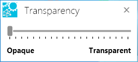
- Adjust the slider until the object is at the desired transparency. To guide you, the transparency of the object in the scene will reflect, in real-time, the adjustments you make.
- Click X to close.
- Right-click an object in the assembly tree to open the assembly context menu (or use CTRL+click or SHIFT+click to select multiple objects, then right-click). You can also select a part or parts in the viewport: Right-click a single part; CTRL+right-click multiple parts.
- Select Render Mode to open the rendering flyout menu.
- Click the desired render mode.
Note
The default render mode setting is Smooth Shading.
- Open the Display menu on the 3D Document Toolbar. (Click the drop-down arrow to the right of the Display icon to see the menu of commands.)

- Click an option to turn on/off display in the viewport.
- Right-click an object in the assembly tree to open the assembly context menu. You can also select a part in the viewport: Right-click a single part.
- Select Align... to start the alignment.
- Select to align by three points or by arc and point.

Align by three points
- Select a point from the selected model.
- Select a respective point on the second model to align the first point on the first model.
- Select a second set of points similar to the first to align the models more.
- Finally, select a thirds set of points to completely align the two models.
Align by arc and point
- Select an arc on the first model.
- Select a respective arc on the second model.
Use the Flip Axis button to align the other side of the arc if not correct.
If the models are aligned, click the Stop button. Otherwise, continue to the final step. - Select respective points from each model to finish the model alignment.
- Right-click an object in the assembly tree to open the assembly context menu (or use CTRL+click or SHIFT+click to select multiple objects, then right-click). You can also select a part or parts in the viewport: Right-click a single part; CTRL+right-click multiple parts.
- Select Transform... to open the Transform dialog box.
- Select the Move tab.
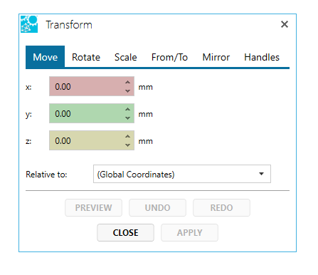
- From the Relative to: drop-down menu, select the coordinate system you want to move with respect to. The default is the current active coordinate system.
- In the X, Y, and Z fields, type the number of units you would like to translate the object along the axes. The units can be positive or negative.
- Click Preview to see what the translation will look like. The object will briefly be translated to the new position and then will return to its original location.
- Click Apply to save the move. The UNDO and REDO buttons become active.
- When you've completed the task, click the CLOSE button.
Note
The units used in a translation are the default units set in the 3D Viewer Settings.
Surfaces cannot be translated. You can only translate an assembly, subassembly, or part.
- Right-click an object in the assembly tree to open the assembly context menu (or use CTRL+click or SHIFT+click to select multiple objects, then right-click). You can also select a part or parts in the viewport: Right-click a single part; CTRL+right-click multiple parts.
- Select Transform... to open the Transform dialog box.
- Select the Rotate tab.
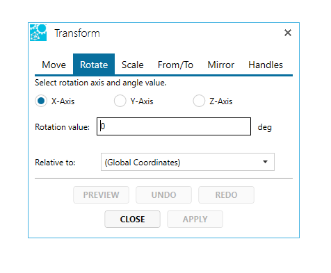
- Select a rotation axis.
- In the Rotation value: box, enter the number of degrees you would like to rotate the object. The value can be positive or negative.
- From the Relative to: drop-down menu, select the coordinate system you want to translate with respect to.
- Click Preview to see what the translation will look like. The object will briefly be translated to the new position and then will return to its original location.
- Click Apply to save the move. The UNDO and REDO buttons become active.
- When you've completed the task, click the CLOSE button.
Note
Surfaces cannot be rotated. You can only rotate an assembly, part, or subassembly.
- Right-click an object in the assembly tree to open the assembly context menu (or use CTRL+click or SHIFT+click to select multiple objects, then right-click). You can also select a part or parts in the viewport: Right-click a single part; CTRL+right-click multiple parts.
- Select Transform... to open the Transform dialog box.
- Select the Scale tab.
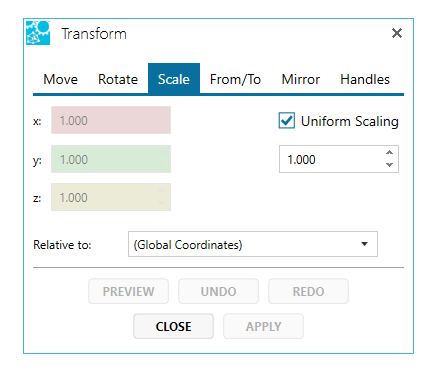
- Check Uniform Scaling if scaling along all three axes equally.
- If unchecked, indicate the scale factor for each axis.
- Otherwise, indicate the uniform scaling factor.
- From the Relative to: drop-down menu, select the coordinate system you want to move with respect to. The default is the current active coordinate system.
- Click Preview to see what the translation will look like. The object will briefly be translated to the new position and then will return to its original location.
- Click Apply to save the move. The UNDO and REDO buttons become active.
- When you've completed the task, click the CLOSE button.
- Right-click an object in the assembly tree to open the assembly context menu (or use CTRL+click or SHIFT+click to select multiple objects, then right-click). You can also select a part or parts in the viewport: Right-click a single part; CTRL+right-click multiple parts.
- Select Transform... to open the Transform dialog box.
- Select the From/To tab.
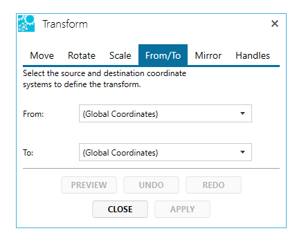
- Select the coordinate system to transform from.
- Select the coordinate system to transform to.
- Click Preview to see what the translation will look like. The object will briefly be translated to the new position and then will return to its original location.
- Click Apply to save the move. The UNDO and REDO buttons become active.
- When you've completed the task, click the CLOSE button.
- Right-click an object in the assembly tree to open the assembly context menu (or use CTRL+click or SHIFT+click to select multiple objects, then right-click). You can also select a part or parts in the viewport: Right-click a single part; CTRL+right-click multiple parts.
- Select Transform... to open the Transform dialog box.
- Select the Mirror tab.

- Select a mirror plane.
- From the Relative to: drop-down menu, select the coordinate system you want to move with respect to. The default is the current active coordinate system.
- Click Preview to see what the translation will look like. The object will briefly be translated to the new position and then will return to its original location.
- Click Apply to save the move. The UNDO and REDO buttons become active.
- When you've completed the task, click the CLOSE button.
- Right-click an object in the assembly tree to open the assembly context menu (or use CTRL+click or SHIFT+click to select multiple objects, then right-click). You can also select a part or parts in the viewport: Right-click a single part; CTRL+right-click multiple parts.
- Select Transform... to open the Transform dialog box.

- Click and drag one of the gripper handles to position your part. Dragging a white dot moves the part along an axis; dragging a red dot rotates the part around it's center axis. Yellow direction arrows appear indicating in which direction you can move the plane. Note that the movement is recorded in the Actions box.

- When you've completed the task, click the CLOSE button.
- Select the parts or assembly either in the graphic area or in the assembly tree.
- Right mouse button click to bring up the context menu.
- Select Re-tessellate....

- Adjust the tessellation settings to accommodate your needs.
- Click Apply when ready to commit the new tessellation.
Tip: Change the render mode of the part or assembly into Triangle Mesh to see the change in tessellation.
Also see Re-Tessellate.
The Minimum Bounding Box calculation finds the dimensions of the smallest box that could surround an object (irrespective of axes alignment).
- Right-click an object in the assembly tree to open the assembly context menu (or use CTRL+click or SHIFT+click to select multiple objects, then right-click). You can also select a part or parts in the viewport: Right-click a single part; CTRL+right-click multiple parts.
- Select Calculate to open the Calculate flyout menu.
- Click Minimum Bounding Box.
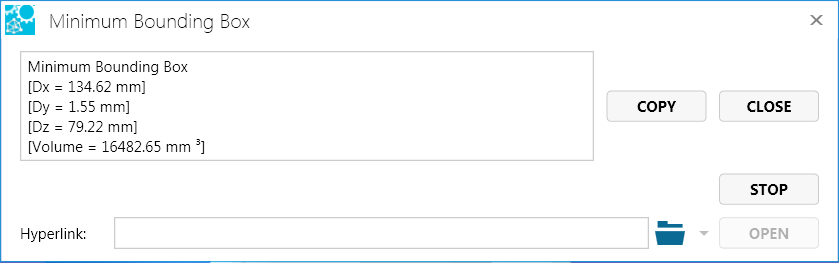
- In addition to the markup, the Minimum Bounding Box information box will display the dimensions and volume of the box and give you the opportunity to link the information to a file.
- Optional: Click Copy to copy the data to the Windows clipboard.
- Optional: Enter a hyperlink to a file or to a document and user view within the current file.
- Click Close to end the command.
- Right-click an object in the assembly tree to open the assembly context menu (or use CTRL+click or SHIFT+click to select multiple objects, then right-click). You can also select a part or parts in the viewport: Right-click a single part; CTRL+right-click multiple parts.
- Select Delete...
- Confirm the deletion.

- Right-click an object in the assembly tree to open the assembly context menu (or use CTRL+click or SHIFT+click to select multiple objects, then right-click). You can also select a part or parts in the viewport: Right-click a single part; CTRL+right-click multiple parts.
- Select Calculate to open the Calculate flyout menu.
- Click Rename…. In the assembly tree, the name of the object is highlighted.
- Enter the new name of the object.
Note
You may also change the name from the Properties dialog box of the object.
More Commands
Right-clicking a model in the 3D scene selects either the part or the surface depending on which picking mode is active.
On the 3D Document Toolbar, click 

- Click the assembly icon in the browser toolbar to view the Assembly browser pane.
- Select an object in the assembly tree (or use CTRL+click or SHIFT+click to select multiple objects).
- Right-click to open the assembly context menu
- Select Transform... to see the Transform dialog box, then select Move or Rotate.
- Enter the appropriate information, click Apply, then OK. You will see the transformation take place in the viewport. See Working with Assemblies and Parts and Assembly Context Menu for details.
- Click the Views icon to see the view tree.
- Double-click User Views to expand the folder.
- To apply geometry information to the view for the first time, right-click the user view item and click Capture Geometry on the flyout menu.
- To update the geometry information, expand the user view item to see the Camera and Geometry subcategories in the Views browser pane, and right-click Geometry. Click Update Geometry on the flyout menu.
Note
It is strongly recommended that you create a "startup" view before applying a transformation to any user view.
If you would like the user view to contain only the part transformations and not a camera position, expand the user view item to see the Camera and Geometry subcategories in the Views browser pane, and right-click Camera. Click Remove Camera on the flyout menu.
- Click the Explode Assembly icon in the 3D toolbar.
- Using the Explode Assembly dialog box, specify the type, direction, part(s), and percentage of the transformation.
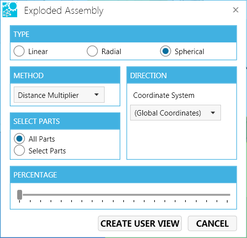
Type:
- Linear - All components move in one direction
- Radial - All components move out from a central axis
- Spherical - All components move out from a central point.
- Select Parts in the assembly.
Percentage - Expand or contract the distance between parts in real time. - Click the Create User View button to save the exploded assembly transformation or Cancel to exit the command.
See also Transforms and User Views
Handy Hint
The easiest way to understand transformation types is to try them.